Adjusting mechanism of crop screening device and adjusting method

A technology of screening device and adjustment mechanism, applied in chemical instruments and methods, sieves, solid separation, etc., can solve the problems of increasing production cost input, etc., and achieve the effect of reducing input and convenient use.

Pending Publication Date: 2018-04-20
TONGXIANG LONGXIANG FARM MACHINERY & GRAIN OIL PROFESSIONAL COOP
0 Cites 1 Cited by

AI-Extracted Technical Summary

Problems solved by technology

The above comparison files exist, and only the same variety of crops can be screened. When different types of crop...

Abstract

The invention relates to an adjustment mechanism and an adjustment method of a crop screening device, belonging to the field of agricultural machinery. When the crops in the prior art are screened, the crops of the same variety need to use the same size of sieve holes. In the present invention, the sieve hole, the cavity and the limiting groove are all arranged on the sieve plate, the cavity is arranged on the inner wall of the sieve hole, the limiting groove is arranged on the bottom surface of the sieve plate, and the limiting groove communicates with the cavity, and the left limit The cavity and the right limit cavity are installed in the cavity, the left limit seat and the right limit seat pass through the limit groove, the left limit cavity cooperates with the right limit cavity, and one side of the baffle plate is installed on the left limit In the position cavity, the other side of the baffle plate is installed in the right limit cavity, one end of the return spring is connected with the material baffle plate, the other end of the return spring is connected with the cavity, the motor is installed at the bottom of the sieve plate, the screw rod and The motor is connected, and the left limit seat and the right limit seat are all sleeved on the screw mandrel. It can be screened for different varieties of crops, when screening different varieties of crops.

Application Domain

SievingScreening

Technology Topic

EngineeringSieve

Image

  • Adjusting mechanism of crop screening device and adjusting method
  • Adjusting mechanism of crop screening device and adjusting method
  • Adjusting mechanism of crop screening device and adjusting method

Examples

  • Experimental program(1)

Example Embodiment

[0024] The present invention will be further described in detail below in conjunction with the accompanying drawings and examples. The following examples are explanations of the present invention and the present invention is not limited to the following examples.
[0025] Example.
[0026] see Figure 1 to Figure 5 It should be noted that the structures, proportions, sizes, etc. shown in the drawings attached to this specification are only used to match the content disclosed in the specification, for those who are familiar with this technology to understand and read, and are not used to limit the present invention Therefore, it has no technical substantive meaning, and any modification of structure, change of proportional relationship or adjustment of size shall still fall into the within the scope covered by the technical content disclosed in the present invention. At the same time, if terms such as "upper", "lower", "left", "right", "middle" and "one" are used in this specification, they are only for the convenience of description and are not used to limit the scope of this specification. The practicable scope of the invention and the change or adjustment of its relative relationship shall also be regarded as the practicable scope of the present invention without any substantial change in the technical content.
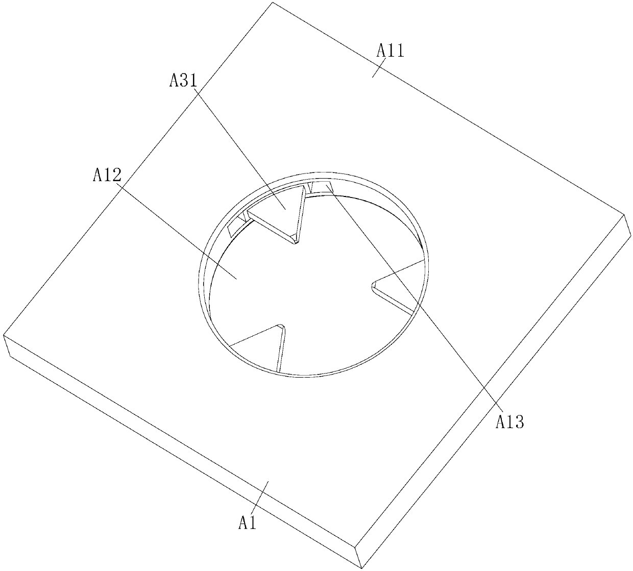
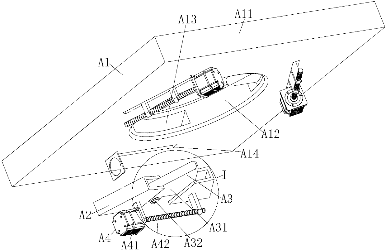
[0027] The adjustment mechanism of the crop screening device in this embodiment includes a sieve plate mechanism A1, a limit mechanism A2, a stopper mechanism A3 and a driving mechanism A4, and the sieve plate mechanism A1 includes a sieve plate A11, a sieve hole A12, a cavity A13 and a limiter. Position slot A14, limit mechanism A2 includes left limit cavity A21, right limit cavity A22, left limit seat A23 and right limit seat A24, material stop mechanism A3 includes material stop plate A31 and return spring A32, drive mechanism A4 Including motor A41 and screw rod A42.
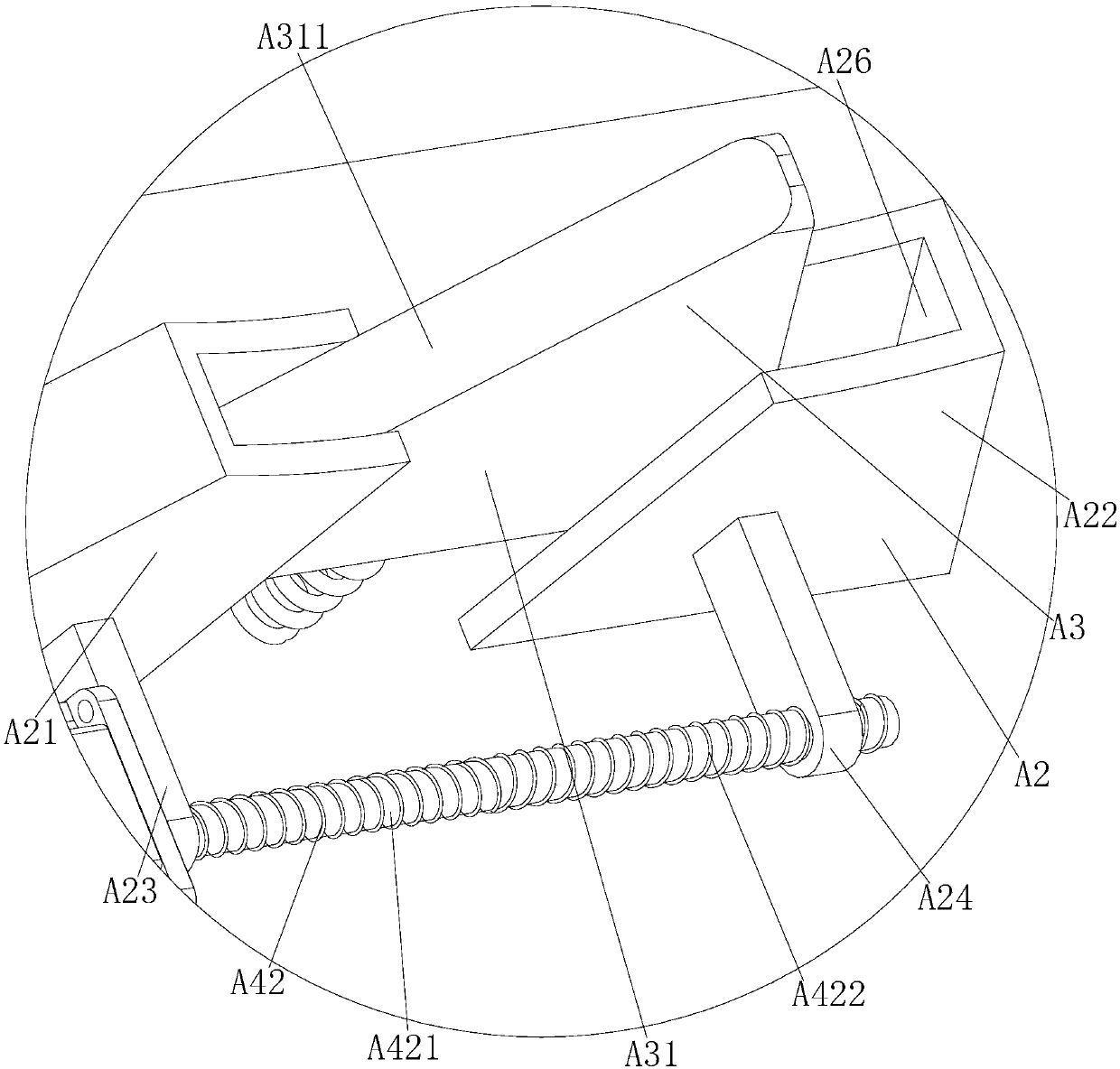
[0028] The sieve hole A12, the cavity A13 and the limit groove A14 in this embodiment are all set on the sieve plate A11, the cavity A13 is set on the inner wall of the sieve hole A12, the limit groove A14 is set on the bottom surface of the sieve plate A11, and limits The bit groove A14 communicates with the cavity A13, the left limiting cavity A21 and the right limiting cavity A22 are installed in the cavity A13, the left limiting seat A23 is installed on the outer wall of the left limiting cavity A21, and the right limiting seat A24 is installed on the outer wall of the left limiting cavity A21. The outer wall of the right limiting cavity A22, the left limiting seat A23 and the right limiting seat A24 all pass through the limiting groove A14, the left limiting cavity A21 cooperates with the right limiting cavity A22, and one side of the material blocking plate A31 is installed on the left In the limiting cavity A21, the other side of the stopper plate A31 is installed in the right limiter cavity A22, one end of the return spring A32 is connected to the stopper plate A31, the other end of the return spring A32 is connected to the cavity A13, and the motor A41 is installed At the bottom of the sieve plate A11, the screw A42 is connected with the motor A41, the left limit seat A23 and the right limit seat A24 are set on the screw A42, and the screw A42 includes a positive thread section A421 and a reverse thread section A422, and the left limit The seat A23 is sleeved on the positive thread section A421, and the right limit seat A24 is sleeved on the reverse thread section A422.
[0029] The return spring A32 in this embodiment is a compression spring; the left limit seat A23 is provided with a positive thread, and the right limit seat A24 is provided with a reverse thread; the inner wall of the left limit chamber A21 is provided with a left limit surface A25, and the right The inner wall of the limiting cavity A22 is provided with a right limiting surface A26.
[0030] The two sides of the baffle plate A31 in the present embodiment are respectively provided with a left contact surface A311 and a right contact surface A312, the left contact surface A311 is in contact with the left limiting surface A25, and the right contact surface A312 is in contact with the right limiting surface A26; A41 is a servo motor; chamfers are provided on the screen holes A12 and the retaining plate A31.
[0031] In this embodiment, there are three cavities A13 and three limiting grooves A14, each cavity A13 is equipped with a limiting mechanism A2, and each limiting mechanism A2 is equipped with a stopper mechanism A3.
[0032] The adjustment method in this embodiment is as follows:
[0033] When screening large-sized crops, the motor A41 drives the screw rod A42 to rotate forward, so that the left limit seat A23 moves to the right, and the right limit seat A24 moves to the left, so that the left limit chamber A21 and the right limit chamber A22 are separated. The adjustment process can be completed by reducing the exposed area of ​​the baffle plate A31 on the sieve hole A12, which can facilitate the screening of large-sized crops;
[0034] When screening small-sized crops, the motor A41 drives the screw rod A42 to reverse, so that the left limit seat A23 moves to the left, and the right limit seat A24 moves to the right, so that the left limit cavity A21 and the right limit cavity A22 are separated. Separation, increasing the exposed area of ​​the baffle plate A31 on the sieve hole A12, can complete the adjustment process, which can facilitate the screening of small-sized crops.
[0035] In this embodiment, the left contact surface A311 is always in contact with the left limiting surface A25, and the right contact surface A312 is always in contact with the right limiting surface A26.
[0036] In this embodiment, the shapes of the cavity A13 , the left limiting cavity A21 and the right limiting cavity A22 are fan-shaped.
[0037]In addition, it should be noted that the specific embodiments described in this specification may be different in parts, shapes and names of components, and the above content described in this specification is only an illustration of the structure of the present invention. All equivalent changes or simple changes made according to the structure, features and principles described in the patent concept of the present invention are included in the protection scope of the patent of the present invention. Those skilled in the art to which the present invention belongs can make various modifications or supplements to the described specific embodiments or adopt similar methods to replace them, as long as they do not deviate from the structure of the present invention or exceed the scope defined in the claims. All should belong to the protection scope of the present invention.

PUM

no PUM

Description & Claims & Application Information

We can also present the details of the Description, Claims and Application information to help users get a comprehensive understanding of the technical details of the patent, such as background art, summary of invention, brief description of drawings, description of embodiments, and other original content. On the other hand, users can also determine the specific scope of protection of the technology through the list of claims; as well as understand the changes in the life cycle of the technology with the presentation of the patent timeline. Login to view more.

Similar technology patents

Early warning system for energy loss prevention based on GIS and big data analysis

PendingCN110737738AImprove inspection qualityreduce investment
Owner:中电万维信息技术有限责任公司

Automatic tube rod conveying machine

Owner:JIANGSU SHENLIDA MACHINERY MFR

Anti-forgery printing ink and manufacturing method thereof

ActiveCN103073951Areduce investment
Owner:广东恒立信息科技有限公司

Classification and recommendation of technical efficacy words

  • reduce investment
  • easy to use

Method for extracting and separating rare earth elements

ActiveUS20100319491A1high separation factorreduce investment
Owner:SHIN ETSU CHEM CO LTD +1

Alarming navigation method and system

InactiveCN102967864ASolve the alarm and call the policereduce investment
Owner:SHENZHEN TCL IND RES INST

Laser assisted total joint arthroplasty

InactiveUS20090234360A1easy to use
Owner:ALEXANDER VLADIMIR

Enclosure for a portable hemodialysis system

ActiveUS20090114582A1easy to use
Owner:DEKA PROD LLP
Why Eureka
Try Eureka