Supercharge Your Innovation With Domain-Expert AI Agents!

A liquid ring pump

A liquid ring pump and housing technology, applied in the field of liquid ring pumps, can solve the problems of multi-working conditions and inconvenient adjustment, and achieve the goals of ensuring stability and fluency, improving use efficiency, improving work performance and work reliability Effect

Active Publication Date: 2019-07-23
LANZHOU UNIVERSITY OF TECHNOLOGY +1
View PDF9 Cites 0 Cited by
  • Summary
  • Abstract
  • Description
  • Claims
  • Application Information

AI Technical Summary

Problems solved by technology

[0004] In order to solve the problems of multiple working conditions and inconvenient adjustments in the current use of liquid ring pumps, the present invention proposes a brand new liquid ring pump

Method used


Image

  • A liquid ring pump
  • A liquid ring pump
  • A liquid ring pump

Examples


Embodiment Construction

[0020] The technical solutions of the present invention will be described in detail below in conjunction with the accompanying drawings.

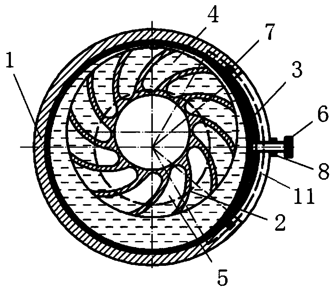
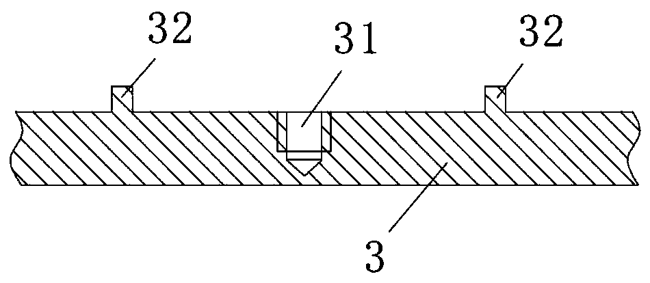
[0021] combine figure 1 As shown, the liquid ring pump of the present invention includes a housing 1 , an impeller 2 and an adjusting sleeve 3 . Wherein, the impeller 2 is located inside the casing 1 and is arranged eccentrically with the casing 1 . The adjusting sleeve 3 is an annular structure located between the housing 1 and the adjusting sleeve 3 , and the adjusting sleeve 3 can rotate relative to the housing 1 along the circumferential direction. At the same time, the outer surface of the adjustment sleeve 3 is in contact with the inner surface of the housing 1, and the wall thickness of the adjustment sleeve 3 is designed to be non-equal thickness along the circumferential direction, that is, the distance between the inner surface of the adjustment sleeve 3 and its central axis, 1. The circumferential direction of the inner surface...


PUM


Abstract

The invention belongs to the technical field of hydraulic machine equipment, and particularly relates to a liquid ring pump. In order to solve the problems that at present, in the use process of the liquid ring pump, many work condition requirements exist, and adjustment is inconvenient, the brand-new liquid ring pump is provided. The liquid ring pump comprises a shell and an impeller. The impeller is located in the shell and arranged eccentrically. An adjusting sleeve is arranged between the shell and the impeller, and the adjusting sleeve and the shell can relatively rotate in the circumferential direction. The adjusting sleeve is of a ring-shaped structure, the outer surface of the adjusting sleeve is in contact with the inner surface of the shell, and the wall thickness of the adjusting sleeve is designed in a different-thickness manner in the circumferential direction. When the liquid ring pump is adopted, the design of multiple shell molded lines can be achieved, multiple characteristic curves can be obtained, and therefore a better adjusting effect can be obtained.

Description

technical field [0001] The invention belongs to the technical field of hydraulic machinery equipment, and in particular relates to a liquid ring pump. Background technique [0002] Liquid ring pumps work similarly to positive displacement pumps, where the impeller is eccentrically placed inside the housing. With the rotation of the impeller, the working medium forms a moving liquid ring on the inner surface of the casing due to inertia, that is, the liquid ring, and at this time, it is formed between the liquid ring, the blade and the impeller hub (or casing) along the circumferential direction. There are several cavities with different volumes, and the volume of each cavity will change periodically with the rotation of the impeller. When the volume of the cavity between the blades is gradually increasing, it communicates with the suction port, and the gas can be inhaled; when the volume of the cavity gradually decreases, the gas will be compressed, and after the impeller r...

Claims


Application Information

Patent Timeline
Patent Type & Authority Patents(China)
IPC IPC(8): F04C19/00F04C28/18
CPCF04C19/00F04C28/18
Inventor 张人会马海涛蒋利杰陈学炳杨军虎王晓晖史凤霞
Owner LANZHOU UNIVERSITY OF TECHNOLOGY
Features
  • R&D
  • Intellectual Property
  • Life Sciences
  • Materials
  • Tech Scout
  • Unparalleled Data Quality
  • Higher Quality Content
  • 60% Fewer Hallucinations
Learn More