Supercharge Your Innovation With Domain-Expert AI Agents!

A differential space modulation transmission method, transmitter and receiver

A technology of spatial modulation and transmission method, applied in the direction of preventing/detecting errors through diversity reception, transmission systems, digital transmission systems, etc., can solve problems such as performance loss, and achieve the effect of improving performance, large diversity gain, and reducing overhead

Active Publication Date: 2022-06-24
BEIJING SAMSUNG TELECOM R&D CENT +1
View PDF5 Cites 0 Cited by
  • Summary
  • Abstract
  • Description
  • Claims
  • Application Information

AI Technical Summary

Problems solved by technology

But the traditional differential spatial modulation will cause performance loss

Method used


Image

  • A differential space modulation transmission method, transmitter and receiver
  • A differential space modulation transmission method, transmitter and receiver
  • A differential space modulation transmission method, transmitter and receiver

Examples


Embodiment 1

[0083] Assume that the differential spatial modulation system has N t = 4 transmit antennas, N r = 2 receiving antennas, the digital modulation method is Quadrature Phase Shift Keying (QPSK);

[0084] Step 1: Determine the index matrix. Since the number of transmit antennas is 4, the index matrix is ​​designed according to the number of transmit antennas being 2. First, the number of transmit antennas is 2 and contains 2 index matrices:

[0085]

[0086] Therefore, in the present invention, the index matrix of the four transmit antennas is:

[0087]

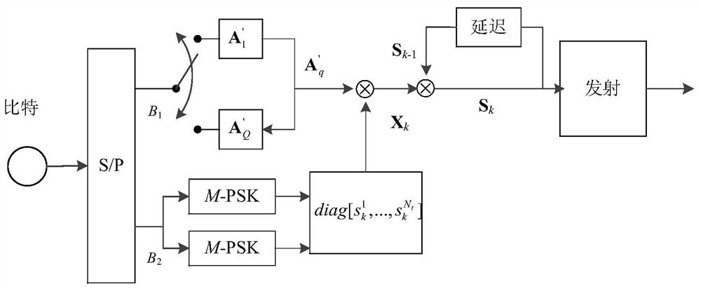
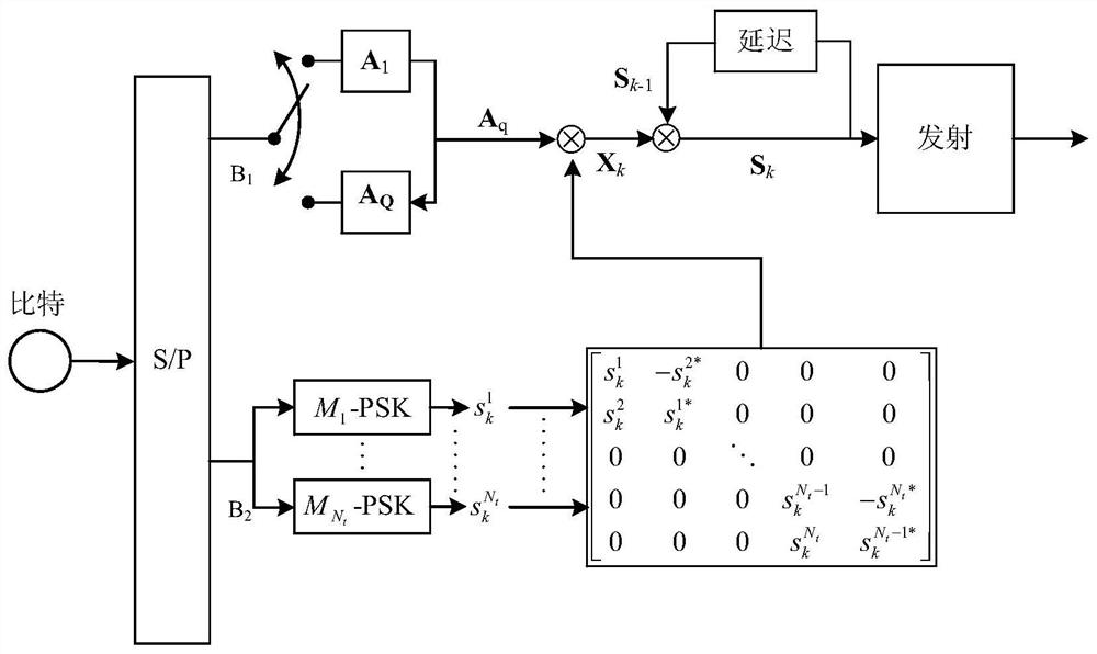
[0088] Step 2: Determine the transmission bits. Matrix S per send k conveys 9 bits of information, where the first bit is used from A 1 and A 2 Select one as the index matrix, and the other 8 bits are used to modulate 4 QPSK symbols {s 1 ,s 2 ,s 3 ,s 4 }.

[0089] Step 3: Do a STBC encoding or SFBC encoding for every two symbols to generate and

[0090] Step 4: According to steps 2 and 3, the k-th symbol ma...

Embodiment 2

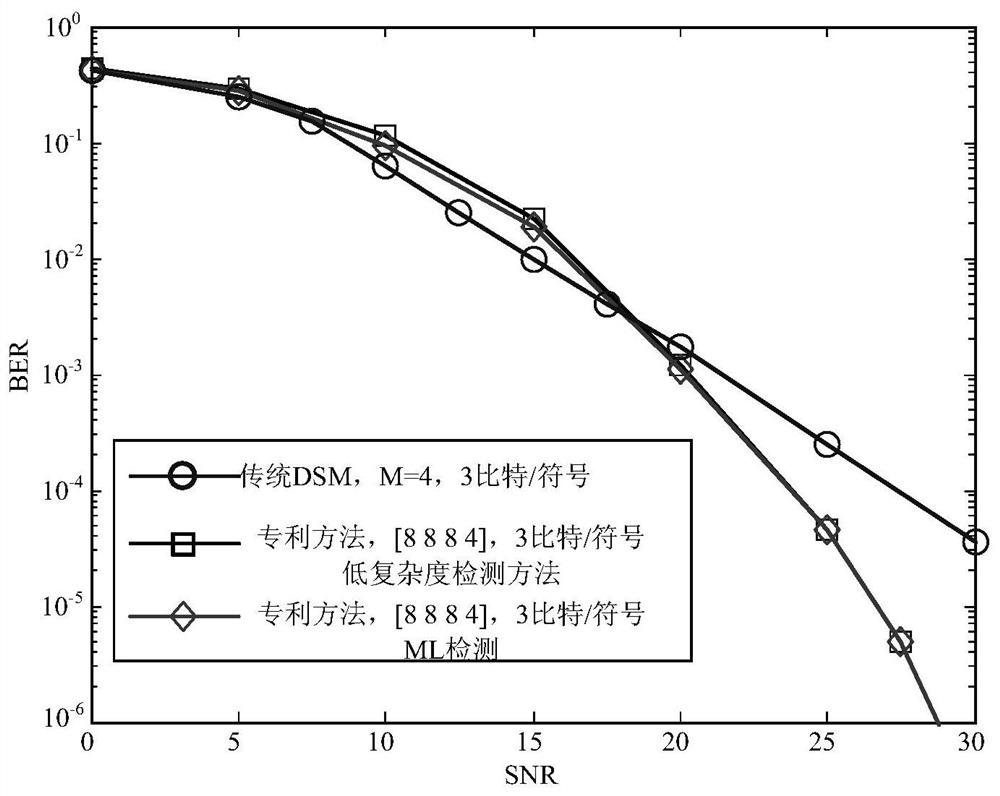
[0095] Assume that the differential spatial modulation system has N t = 16 transmit antennas, N r = 2 receiving antennas, and the modulation method is QPSK; more transmitting antennas make the maximum likelihood detection extremely complicated and impractical, and this embodiment adopts the low-complexity detection algorithm proposed by the present invention.

[0096] Step 1: Determine the index matrix. Since the number of transmit antennas is 16, the index matrix is ​​designed according to the number of transmit antennas being 8. The number of transmit antennas is 8, including index matrix, where is the round-down function.

[0097] Step 2: Determine the transmission bits. Matrix S per send k conveys 47 bits of information, of which the first 15 bits are used from matrix A q ,q∈(1,2 15 ) as the index matrix, and the last 32 bits are used to modulate 16 QPSK symbols {s 1 ,s 2 ,…,s 16 }.

[0098] Step 3: Do a STBC encoding or SFBC encoding for every two symbols to...


PUM


Abstract

The present application discloses a differential spatial modulation transmission method, including: constructing an index matrix A according to an index matrix of dimension q ,q∈(1,Q), where N t is the number of transmitting antennas, N is the dimension of the coding matrix of the coding technology used; it is a function of rounding down; the differential space modulation transmission information bits are divided into two parts: the first part of information bits and the second part of information bits; use the first part The information bit is mapped to an index matrix; the second part of the information bit is used to map the constellation symbol; the constellation symbol is space-time coded to obtain a symbol matrix block; according to the transmission matrix block and the symbol matrix block, differential coding is performed to obtain a differentially coded transmission matrix block; The resulting transmission matrix blocks are transmitted by the transmit antennas. The invention also discloses a data receiving method corresponding to the above transmission method, a transmitter and a receiver. By applying the technical solution disclosed in this application, the performance of the differential spatial modulation system can be improved, and the overhead caused by the reference signal can be reduced.

Description

technical field [0001] The present application belongs to the technical field of communication anti-interference, and relates to technologies such as Differential Spatial Modulation (DSM) technology, space-time coding, and Multiple Input Multiple Output (MIMO), and in particular, to a combined space-time Coded differential spatial modulation transmission method, transmitter and receiver. Background technique [0002] Spatial Modulation (SM) technology is a new MIMO transmission technology proposed in recent years, which can also be regarded as a new modulation technology using antenna resources. The basic principle is: by activating different transmit antennas, the index values ​​of the activated antennas are used to modulate the bit information. Only one antenna is activated in each time slot of spatial modulation, which can effectively avoid the problems of multi-antenna interference and synchronization between transmit antennas in traditional MIMO systems, and reduce the...

Claims


Application Information

Patent Timeline
Patent Type & Authority Patents(China)
IPC IPC(8): H04L1/06
CPCH04B7/0456H04B7/0697H04B7/0891H04L1/0612H04L1/0618H04L1/0681
Inventor 肖丽霞刘江肖悦钱辰喻斌
Owner BEIJING SAMSUNG TELECOM R&D CENT
Features
  • R&D
  • Intellectual Property
  • Life Sciences
  • Materials
  • Tech Scout
  • Unparalleled Data Quality
  • Higher Quality Content
  • 60% Fewer Hallucinations
Learn More