Split cell breaker

A crusher and split-type technology, applied in biochemical instruments, biochemical equipment and methods, enzymology/microbiology devices, etc., can solve problems such as damaged parts, easy tearing at B, and equipment failure, etc., to achieve Simplified structure, reduced production cost and development difficulty, and simple installation

Pending Publication Date: 2018-04-27
GUANGZHOU JUNENG BIOLOGY & TECH
View PDF0 Cites 0 Cited by
  • Summary
  • Abstract
  • Description
  • Claims
  • Application Information

AI Technical Summary

Problems solved by technology

It can be seen from the above that point B becomes the damage point of the equipment; under long-term work, it

Method used


Image

  • Split cell breaker
  • Split cell breaker
  • Split cell breaker

Examples


Example Embodiment

[0029] Example

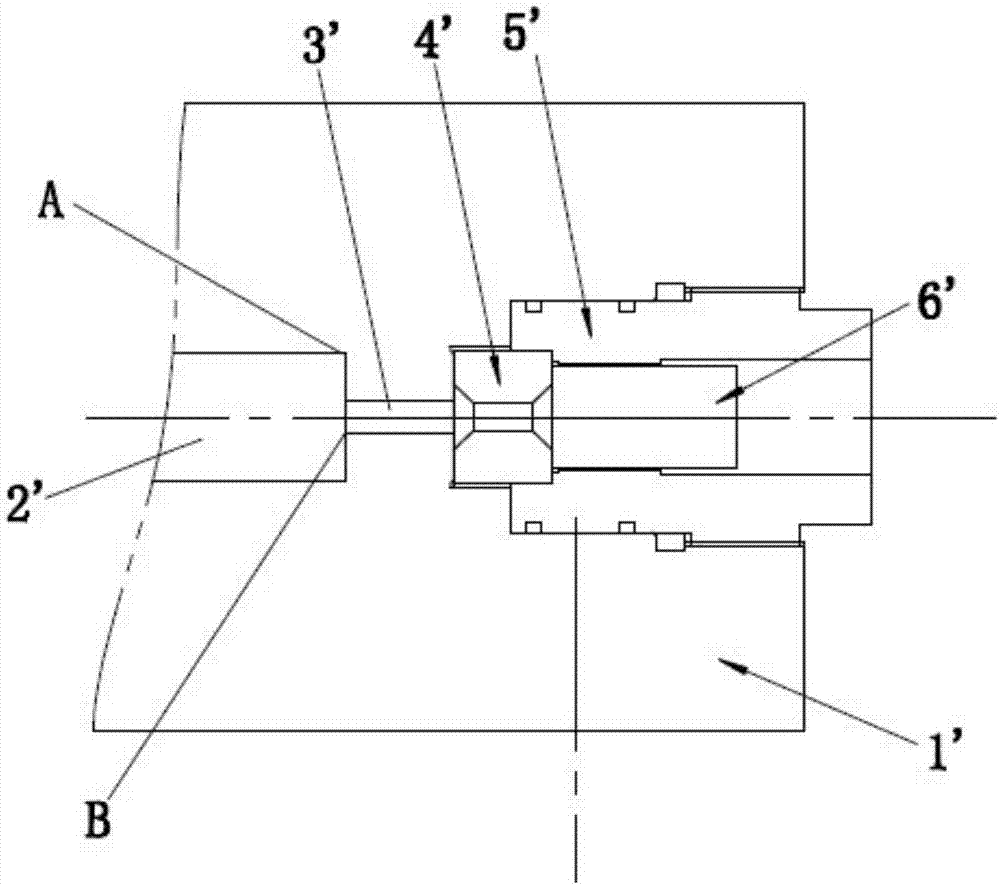
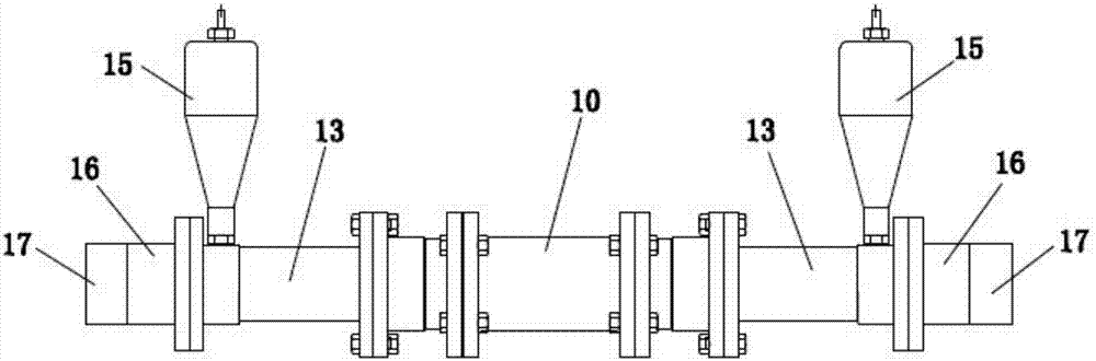
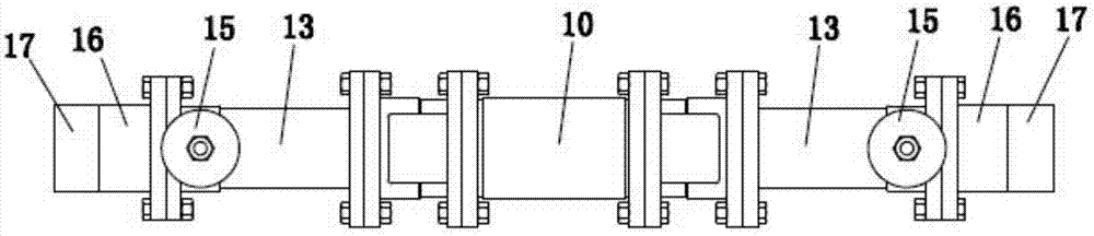
[0030] The specific embodiments of the present invention are as Figure 2 to Figure 5 As shown, a split cell crusher includes a high-pressure cylinder 13 connected with a hopper 15 on one side. One end of the high-pressure cylinder 13 is connected with a piston cylinder 10, and the other end of the high-pressure cylinder 13 is connected with a crusher 16 and a hydraulic cylinder 17 in sequence. The crusher 16 includes a cylinder 1 with a first material passage 2 whose input end is connected to a high-pressure cylinder 13, and a central part connected in sequence along the output end of the first material passage 2 in the cylinder 1 The communicating nest 7, the valve seat 4 and the guide sleeve 5 are communicated with the hydraulic cylinder 17. The guide sleeve 5 is provided with a valve core 6 on one side of the valve seat 4. The hydraulic cylinder 17 provides pressure to one end of the valve core 6 so that the other end of the valve core 6 is pressed against t...


PUM


Abstract

The invention discloses a split cell breaker. The split cell breaker comprises high-pressure cylinders, one side of each high-pressure cylinder is connected with a hopper, a piston cylinder is connected to one end of each high-pressure cylinder, and the other end of each high-pressure cylinder is connected with a breaking device and a hydraulic cylinder. Each breaking device comprises a cylinder body which is internally provided with a first material passage, an embedding sleeve, a valve seat and a guide sleeve are sequentially arranged in each cylinder body along an output end of the corresponding first material passage, and middles of each embedding sleeve, the corresponding valve seat and the corresponding guide sleeve are communicated. A valve core is arranged in each guide sleeve, each embedding sleeve is arranged between the corresponding cylinder body and the corresponding guide sleeve, and one end, facing the corresponding first material passage, of each embedding sleeve is provided with an embedding end. The middle of each embedding end is provided with a second material passage, and the diameter of each second material passage is smaller than that of each first material passage. The split cell breaker has advantages that the problem of stress concentration at the joint of an end face platform and one end of a second material passage in a traditional structure is avoided, and service lives of parts and the breaker are prolonged.

Description

technical field [0001] The invention relates to the field of cell crushing equipment, in particular to a split cell crushing machine. Background technique [0002] In the cell breaking device, the cell breaking device is an important part, which is used to break the cell material entering it. Current cell disruptors such as figure 1 As shown, it mainly includes a cylinder body 1', which is provided with a first material channel 2', a second material channel 3', a valve seat 4' and a guide sleeve 5 arranged in sequence along the direction of material movement. ', the guide sleeve 5' is provided with a valve core 6' located on the side of the valve seat 4'. Wherein, both the first material channel 2' and the second material channel 3' are formed on the cylinder body 1', and the cross-sectional size of the first material channel 2' is larger than that of the second material channel 3', so the connection between the two forms an end surface platform. [0003] Such as figure...

Claims


Application Information

Patent Timeline
IPC IPC(8): C12M1/33
CPCC12M35/04Y02W30/62
Inventor 余行文
Owner GUANGZHOU JUNENG BIOLOGY & TECH
Why Eureka
Try Eureka