Exhaust gas recirculation system

A recirculation system, a technology of the circulation system, applied in the directions of gas treatment, combustion product treatment, combustion method, etc., can solve problems such as environmental pollution, waste of nitric acid resources, ozone layer destruction, etc., achieve good spray effect, reduce emissions, Even spray effect

Inactive Publication Date: 2018-05-01
浙江千尧环境工程有限公司
View PDF5 Cites 4 Cited by
  • Summary
  • Abstract
  • Description
  • Claims
  • Application Information

AI Technical Summary

Problems solved by technology

[0002] my country is a large energy consumption country. After burning fossil fuels, a large amount of flue gas is emitted. In various nitric acid industries, a large amount of flue gas containing nitric acid will be produced. The sulfur dioxide, nitrogen o

Method used


Image

  • Exhaust gas recirculation system
  • Exhaust gas recirculation system
  • Exhaust gas recirculation system

Examples


Example Embodiment

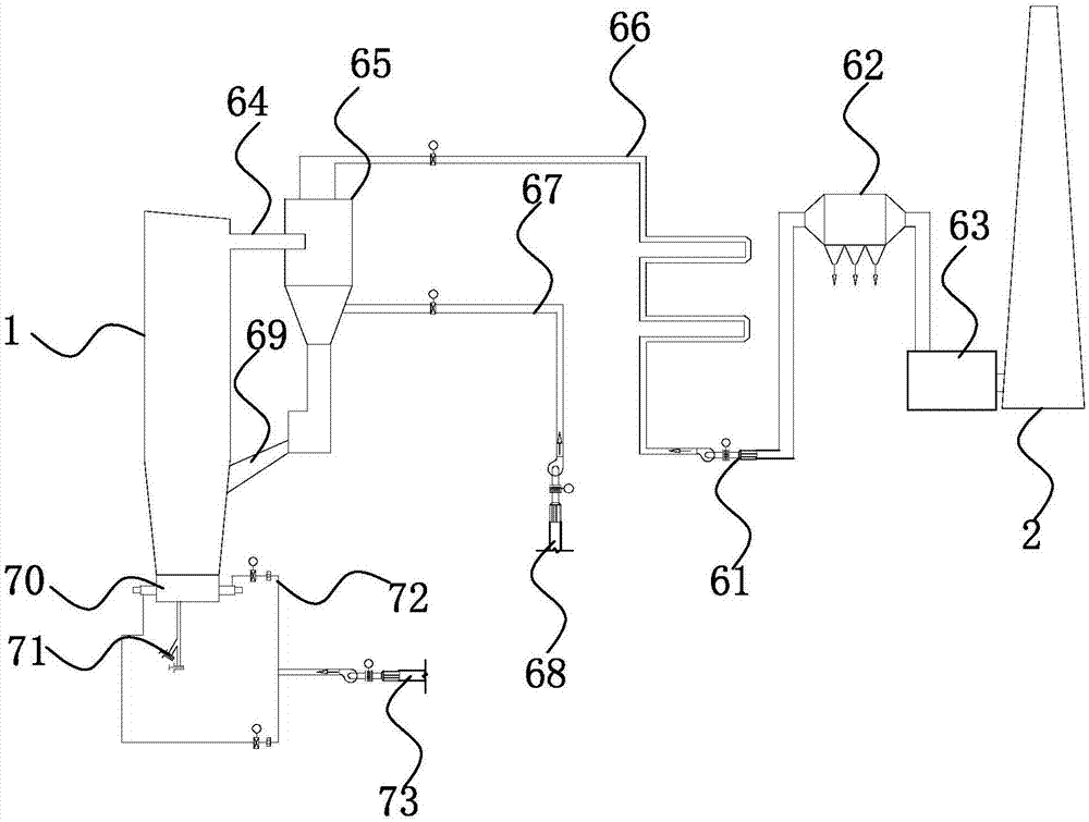
[0038] Example 1: A flue gas recirculation system, such as figure 1 , Including circulating fluidized bed boiler 1, circulating fluidized bed boiler 1 is connected to flue 64, flue 64 is connected to cyclone separator 65, the top of cyclone separator 65 is connected to induced draft fan 61 through curved network pipe 66, and induced draft fan 61 is connected to dust collector 62 The dust collector 62 is connected to the chimney 2 through the desulfurization device 63; the side wall of the cyclone separator 65 is connected to the sweeping fan 68 through a right-angle pipe 67, and the bottom of the cyclone separator 65 is connected to the circulating fluidized bed boiler 1 through an ash pipe connection 69.

[0039] The bottom of the circulating fluidized bed boiler 1 is provided with a cooling cycle system. The cooling cycle system includes a cooling chamber 70 arranged at the bottom of the circulating fluidized bed boiler 1. A circulating pipe 72 is provided on the side wall of the...

Example Embodiment

[0048] Embodiment 2: A flue gas recirculation system, such as Figure 5 The difference from the first embodiment is that: a return pipe 15 is provided on the curved network pipe 66, one end of the return pipe 15 is connected to the curved network pipe 66, and the other end is connected to the circulating fluidized bed boiler 1; the flue gas enters the curved network pipe 66 and passes After multiple rotations and cooling, it is returned to the circulating fluidized bed boiler 1 by the return pipe 15 to reduce the production of flue gas nitrogen oxides, thereby effectively improving the production of harmful substances in the flue gas, and then discharge after dust removal treatment, which has little air pollution.


PUM


Abstract

The invention discloses an exhaust gas recirculation system, which comprises a circulating fluidized bed boiler and a chimney, wherein the circulating fluidized bed boiler is provided with a recirculation system, the recirculation system is connected to a draught fan, the draught fan is connected to a dust remover, the dust remover is connected to the chimney through a desulfurizer, and a coolingcirculation system is arranged on the bottom of the circulating fluidized bed boiler; the recirculation system comprises a flue arranged in connection with the circulating fluidized bed boiler, and acyclone separator arranged in connection with the flue, the top of the cyclone separator is connected to the draught fan through a bent mesh pipe, a sidewall of the cyclone separator is connected to acleaning fan through a right-angled pipeline, and the bottom of the cyclone separator is connected to the circulating fluidized bed boiler through an ash conveying pipe. In the exhaust gas recirculation system, exhaust gas is dynamically circulated by the recirculation system, and is effectively cooled in the process of circulation, moreover, harmful components in the gas are effectively adsorbedand filtered, the treated gas can be directly emitted, and the treatment effect is good.

Description

technical field [0001] This invention relates to exhaust gas treatment devices and, more particularly, to flue gas recirculation systems. Background technique [0002] my country is a large energy consumption country. After burning fossil fuels, a large amount of flue gas is emitted. In various nitric acid industries, a large amount of flue gas containing nitric acid will be produced. The sulfur dioxide, nitrogen oxides and other acid gases and fine particle dust contained in the flue gas will The environment causes smog, acid rain, enhanced greenhouse effect and destruction of the ozone layer, causing serious environmental pollution and waste of nitric acid resources. Contents of the invention [0003] In view of the deficiencies in the prior art, the purpose of the present invention is to provide a flue gas recirculation system, which can effectively absorb and filter harmful components in the gas, and the treated gas can be discharged directly, with good treatment effect...

Claims


Application Information

Patent Timeline
IPC IPC(8): B01D50/00B01D53/50B01D53/60B01D53/75B01D53/78B01D53/82F23C10/10F23J15/02F23J15/04
CPCB01D50/00B01D53/502B01D53/60B01D53/75B01D53/78B01D53/82B01D2251/304B01D2253/102B01D2257/302B01D2257/40F23C10/10F23J15/025F23J15/04F23J2215/10
Inventor 王懿翔阮徐均陈尼青
Owner 浙江千尧环境工程有限公司
Why Eureka
Try Eureka