Novel wireless endoscope
An endoscope and wireless technology, applied in the field of medical endoscopy, can solve the problems of fragile optical fiber, high cost, and narrow application range of capsule endoscopy, and achieve the effect of multi-angle adjustment and angle change
- Summary
- Abstract
- Description
- Claims
- Application Information
AI Technical Summary
Problems solved by technology
Method used
Image


Examples
Embodiment 1
[0036] Embodiment 1 A novel wireless endoscope
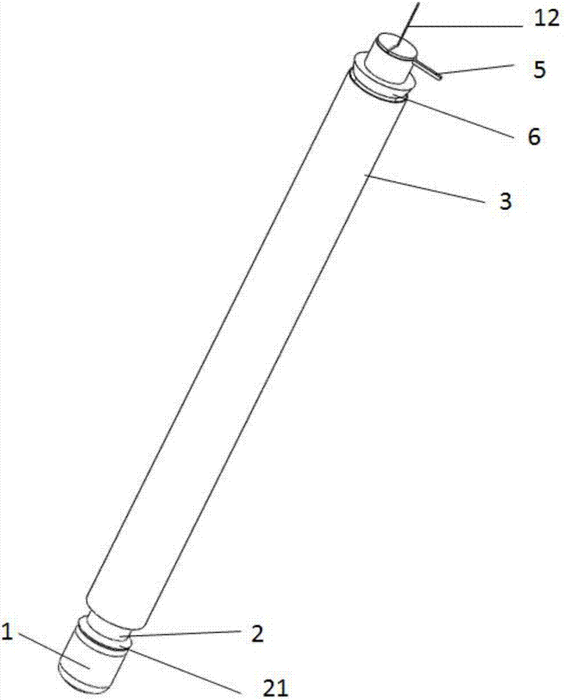
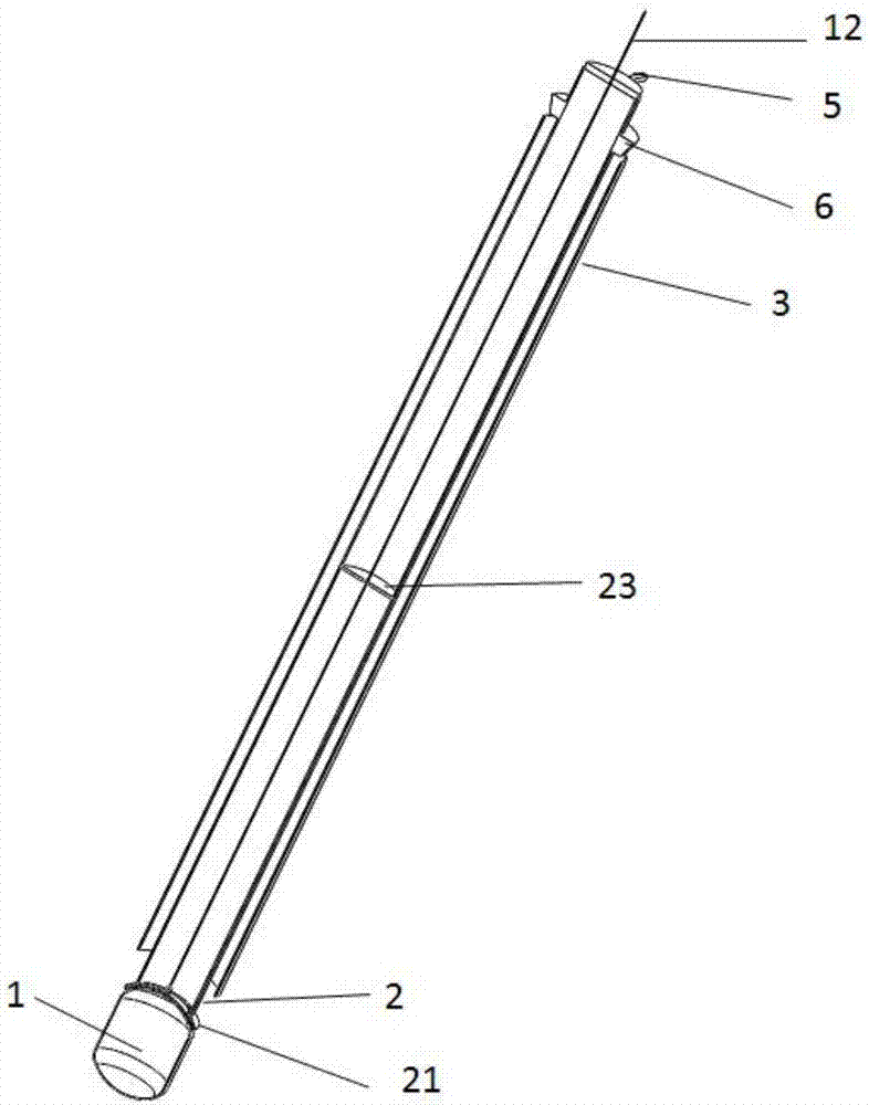
[0037]A new type of wireless endoscope, which includes a capsule endoscope 1, an inner sleeve 2 and an outer sleeve 3; wherein, the rear end of the capsule endoscope 1 is provided with a magnetic material that is connected to the rear end of the capsule endoscope 1 An anastomotic arc cover 11; a combination cover 21 corresponding to the shape of the arc cover 11 and made of paramagnetic material is provided at the front end of the inner sleeve 2; a rotatable extension handle 12 is provided at the top of the arc cover 11; the combination cover 21 An active hole 22 is arranged on the top; the extension handle 12 is directly extended to the rearmost end of the inner sleeve 2 and protrudes from the rear end of the inner sleeve 2; the middle part of the inner sleeve 2 is provided with a limiter that controls the position of the extension handle 12 and serves as a movable fulcrum Structure; the inner casing 2 is arranged inside the ou...
Embodiment 2
[0041] Embodiment 2 A new type of wireless endoscope
[0042] A new type of wireless endoscope, which includes a capsule endoscope 1, an inner sleeve 2 and an outer sleeve 3; wherein, the rear end of the capsule endoscope 1 is provided with a magnetic material that is connected to the rear end of the capsule endoscope 1 An anastomotic arc cover 11; a combination cover 21 corresponding to the shape of the arc cover 11 and made of paramagnetic material is provided at the front end of the inner sleeve 2; a rotatable extension handle 12 is provided at the top of the arc cover 11; the combination cover 21 An active hole 22 is arranged on the top; the extension handle 12 is directly extended to the rearmost end of the inner sleeve 2 and protrudes from the rear end of the inner sleeve 2; the middle part of the inner sleeve 2 is provided with a limiter that controls the position of the extension handle 12 and serves as a movable fulcrum Structure; the inner casing 2 is arranged inside...
Embodiment 3
[0046] Embodiment 3 A new type of wireless endoscope
[0047] A new type of wireless endoscope, which includes a capsule endoscope 1, an inner sleeve 2 and an outer sleeve 3; wherein, the rear end of the capsule endoscope 1 is provided with a magnetic material that is connected to the rear end of the capsule endoscope 1 An anastomotic arc cover 11; a combination cover 21 corresponding to the shape of the arc cover 11 and made of paramagnetic material is provided at the front end of the inner sleeve 2; a rotatable extension handle 12 is provided at the top of the arc cover 11; the combination cover 21 An active hole 22 is arranged on the top; the extension handle 12 is directly extended to the rearmost end of the inner sleeve 2 and protrudes from the rear end of the inner sleeve 2; the middle part of the inner sleeve 2 is provided with a limiter that controls the position of the extension handle 12 and serves as a movable fulcrum Structure; the inner casing 2 is arranged inside...
PUM
 Abstract
Description
Claims
Application Information
 - Generate Ideas
- Intellectual Property
- Life Sciences
- Materials
- Tech Scout
- Unparalleled Data Quality
- Higher Quality Content
- 60% Fewer Hallucinations
Browse by: Latest US Patents, China's latest patents, Technical Efficacy Thesaurus, Application Domain, Technology Topic, Popular Technical Reports.
© 2025 PatSnap. All rights reserved.Legal|Privacy policy|Modern Slavery Act Transparency Statement|Sitemap|About US| Contact US: help@patsnap.com