Check patentability & draft patents in minutes with Patsnap Eureka AI!

Linear anisotropic magnetoresistive sensor and preparation method thereof

An anisotropic magnetic and sensor technology, used in instruments, measuring magnetic variables, measuring devices, etc., can solve the problem of less noise in the output signal of the conductive layer, and achieve the effect of clear current direction, less noise in the output signal, and thin conductive layer.

Inactive Publication Date: 2018-06-01
UNIV OF ELECTRONICS SCI & TECH OF CHINA
View PDF7 Cites 3 Cited by
  • Summary
  • Abstract
  • Description
  • Claims
  • Application Information

AI Technical Summary

Problems solved by technology

[0006] In view of the above existing problems or deficiencies, in order to realize the technical problems of the linear anisotropic magnetoresistive sensor under the premise of ensuring the current bias effect, the conductive layer is thinner and the output signal noise is less; the present invention provides a linear anisotropic magnetoresistive sensor. Magnetoresistive sensor and its preparation method

Method used


Image

  • Linear anisotropic magnetoresistive sensor and preparation method thereof
  • Linear anisotropic magnetoresistive sensor and preparation method thereof
  • Linear anisotropic magnetoresistive sensor and preparation method thereof

Examples


Embodiment Construction

[0026] The technical scheme of the present invention will be described in detail below in conjunction with the accompanying drawings and embodiments.

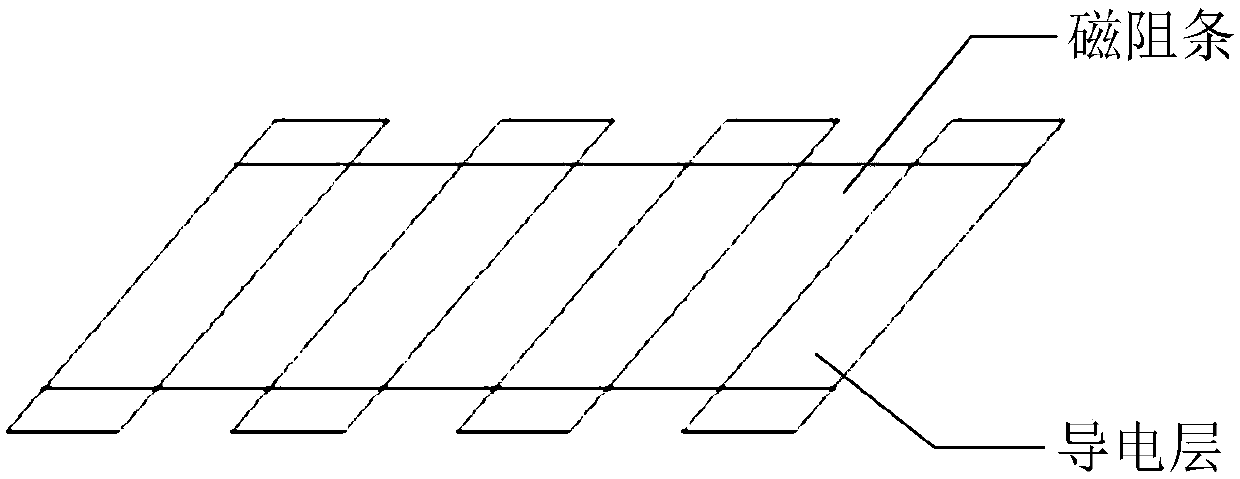
[0027] Step 1: On the silicon substrate, a pattern of elongated magnetoresistive strips with a total length of 7.2um and discontinuous strips is exposed by a photolithography process, each magnetoresistive strip has a width of 5nm and a gap of 5nm.

[0028] Step 2: Deposit 5nmTa, 12nmNiFe and 2nmTa in sequence on the substrate treated in step 1 by magnetron sputtering process. Then it is soaked in the glue removing solution, and after the photoresist is removed, the sample is taken out to obtain discontinuous elongated magnetoresistive strips.

[0029] Step 3: On the substrate processed in step 2, a 20nm Al conductive layer is filled at the position of the non-magnetoresistive strips by using a photolithography process and an electron beam evaporation process, and the magnetoresistive strips are electrically connected through t...


PUM


Abstract

The invention belongs to the technical field of magnetic material and components, and particularly provides a linear anisotropic magnetoresistive sensor and a preparation method thereof. N parallelogram reluctance bars which are not connected and N-1-N+1 parallelogram conductive layers which are not connected are laid on the same horizontal plane of a substrate in a mutually staggered mode. The reluctance bars are enabled to be electrically connected through the embedded conductive layers so that the current direction of all the reluctance parts is enabled to be identical and clear, and the noise of the output electric signals can be obviously reduced. The conductive layers embedded in the reluctance bars can change the current direction without the basis of thickness so that the thicknessof the whole device can be reduced and the structural stability can be enhanced. Finally the thinner conductive layers and the less noise of the output signals can be realized under the premise of guaranteeing the current offset effect.

Description

technical field [0001] The invention belongs to the technical field of magnetic materials and components, in particular to a linear anisotropic magnetoresistance sensor and a preparation method thereof. Background technique [0002] Anisotropic magnetoresistance effect (AMR, Anisotropic Magnetoresistance) means that in magnetic materials (such as NiFe, CoFe, Co, etc.), when the angle between the magnetic moment of the magnetic material and the current changes, the resistance of the material also changes. The phenomenon. The size R of the anisotropic magnetoresistance satisfies: R=R 0 +ΔRcos2θ, where R 0 is the resistance value under zero magnetic field; ΔR is the maximum change value of anisotropic magnetoresistance; θ is the angle between the current direction and the magnetization direction of the magnetic layer. The linear anisotropic magnetoresistive sensor is based on the anisotropic magnetoresistance effect. Under specific preparation conditions, the orientation of ...

Claims


Application Information

Patent Timeline
Patent Type & Authority Applications(China)
IPC IPC(8): G01R33/09G01R33/00
CPCG01R33/00G01R33/09
Inventor 张万里胡凌桐张文旭彭斌
Owner UNIV OF ELECTRONICS SCI & TECH OF CHINA
Features
  • R&D
  • Intellectual Property
  • Life Sciences
  • Materials
  • Tech Scout
  • Unparalleled Data Quality
  • Higher Quality Content
  • 60% Fewer Hallucinations
Learn More