Supercharge Your Innovation With Domain-Expert AI Agents!

Longitudinal-bar and I-steel-beam connection node and section-steel-beam-column connection structure

A technology of I-beam and connecting nodes, applied in the direction of structural elements, building components, building structures, etc., can solve the problems of inconvenient on-site construction, affecting the structural strength and stability, increasing the processing difficulty of steel components, etc., to reduce the installation. Difficulty, saving labor costs, and improving construction efficiency

Active Publication Date: 2018-06-08
KOCEL STEEL STRUCTURE CO LTD
View PDF9 Cites 1 Cited by
  • Summary
  • Abstract
  • Description
  • Claims
  • Application Information

AI Technical Summary

Problems solved by technology

[0004] The purpose of the present invention is to provide a connection node between longitudinal reinforcement and I-beam to solve the problems in the prior art that the form of perforation on the beam affects the structural strength and stability, increases the difficulty of steel member processing, and is not convenient for on-site construction

Method used


Image

  • Longitudinal-bar and I-steel-beam connection node and section-steel-beam-column connection structure
  • Longitudinal-bar and I-steel-beam connection node and section-steel-beam-column connection structure
  • Longitudinal-bar and I-steel-beam connection node and section-steel-beam-column connection structure

Examples


Embodiment

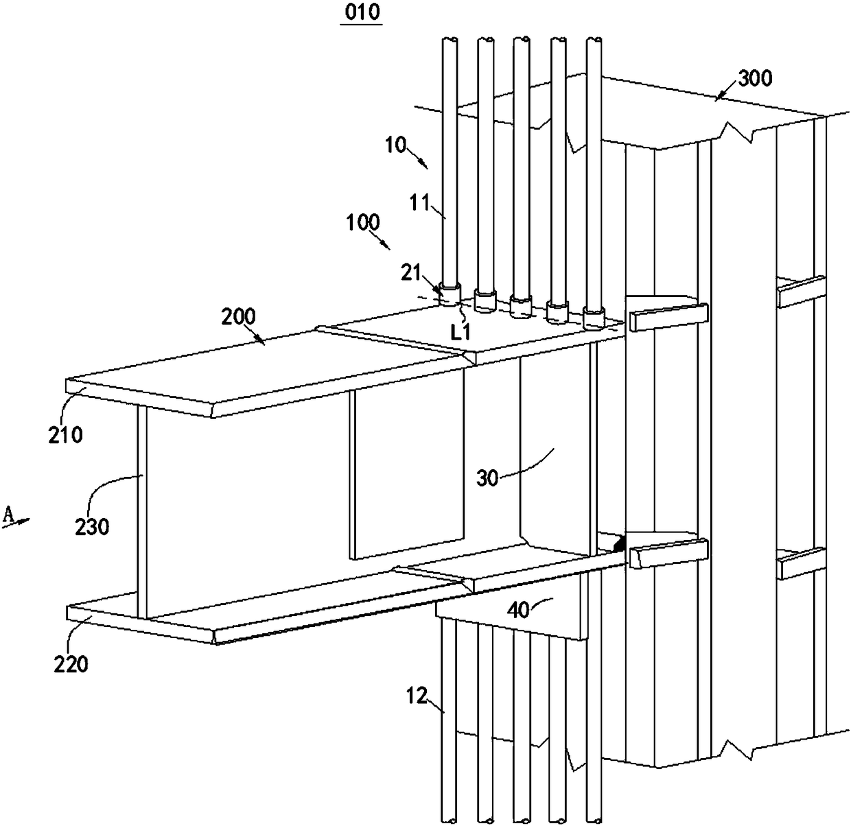
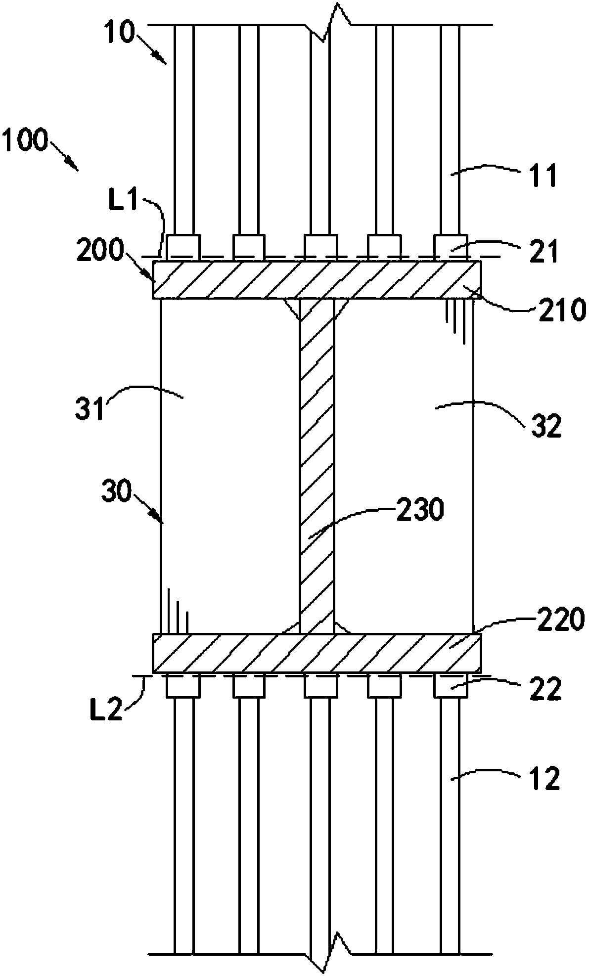
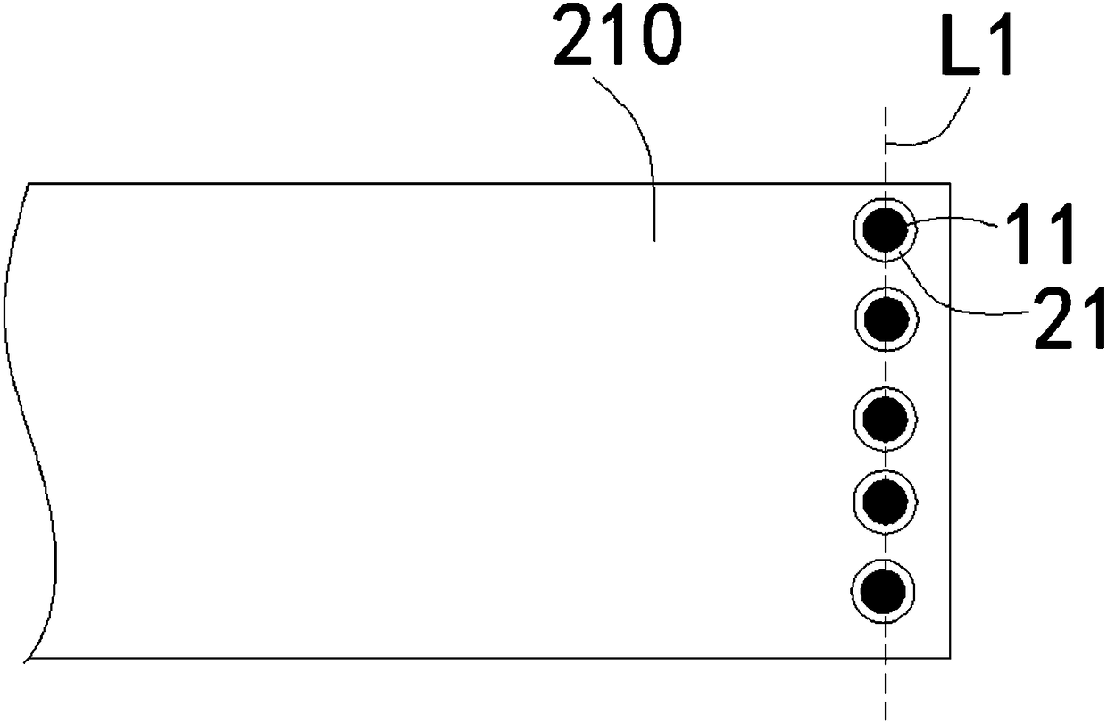
[0043] figure 1 It is a structural schematic diagram of the steel beam-column connection structure 010 in the embodiment of the present invention; figure 2 for figure 1 View along direction A (partial structure hidden). see figure 1 , figure 2, the steel beam-column connection structure 010 in this embodiment includes a steel column 300 , an I-beam 200 , and longitudinal bars 10 . The I-beam 200 is vertically connected to the side of the steel column 300 . The longitudinal reinforcement 10 is located outside the steel column 300 and vertically connected to the I-beam 200 . The connection between the longitudinal reinforcement 10 and the I-shaped steel beam 200 adopts the connection node 100 between the longitudinal reinforcement and the I-shaped steel beam.

[0044] The structure of the connection node 100 between the longitudinal reinforcement and the I-shaped steel beam in the present embodiment is as follows:

[0045] The upper surface of the upper wing plate 210 o...


PUM


Abstract

The invention relates to the field of building structures. A longitudinal-bar and I-steel-beam connection node and a section-steel-beam-column connection structure aim at solving the problems that inan existing punching-on-beam mode, the structural strength and the stability are influenced, the processing difficulty of a steel member is increased, and site construction is inconvenient. A plurality of upper sleeves are fixedly connected on the upper surface of an upper flange of an I steel steam, a plurality of lower sleeves are fixedly connected on the lower surface of a lower flange of the Isteel steam, and the upper sleeves are right opposite to the lower sleeves in the vertical direction; a longitudinal bar comprises upper longitudinal bar bodies and lower longitudinal bar bodies, thelower ends of the upper longitudinal bar bodies are fixedly connected to the upper sleeves and extend upwards in the vertical direction, and the upper ends of the lower longitudinal bar bodies are fixedly connected to the lower sleeves and extend downwards in the vertical direction; a vertical supporting plate is supported between the upper flange and the lower flange, and in projection of the same horizontal plane, projection of the vertical supporting plate at lease comprises projection of the upper sleeves and projection of the lower sleeves. The longitudinal-bar and I-steel-beam connection node and the section-steel-beam-column connection structure have the advantages that hole opening on an I steel steam is not required as the prior art, the installing difficulty of a construction site is reduced, whole construction efficiency is improved, and the labor cost is greatly saved.

Description

technical field [0001] The invention relates to the field of building structures, in particular to a connection node between a longitudinal bar and an I-shaped steel beam and a steel beam-column connection structure. Background technique [0002] The steel concrete structure refers to the structure in which steel bars are arranged around the steel and concrete is poured, and it is a form of composite structure. Compared with reinforced concrete structures, steel concrete structures have the characteristics of high strength, high rigidity and good ductility, so they are especially suitable for buildings in earthquake zones, especially high-rise and super high-rise buildings. Because the high-rise and super-high-rise buildings in the earthquake zone adopt reinforced concrete structure, its ductility and seismic performance often cannot meet the requirements. However, if the steel concrete structure is adopted, it not only has sufficient anti-seismic performance, but also the ...

Claims


Application Information

Patent Timeline
Patent Type & Authority Applications(China)
IPC IPC(8): E04B1/30E04B1/58E04C5/16
CPCE04B1/185E04B1/30E04C5/165
Inventor 陶雄壮张昆
Owner KOCEL STEEL STRUCTURE CO LTD
Features
  • R&D
  • Intellectual Property
  • Life Sciences
  • Materials
  • Tech Scout
  • Unparalleled Data Quality
  • Higher Quality Content
  • 60% Fewer Hallucinations
Learn More