Compound functional cavity mechanism suitable for metal three-dimensional printing post-processing

A 3D printing and composite function technology, applied in the direction of improving energy efficiency, process efficiency, additive manufacturing, etc., can solve the problems of high porosity of metal 3D printing parts, complex post-processing procedures, low strength and hardness, etc., to achieve Reduce post-processing procedures, improve overall performance, and increase strength and hardness

Pending Publication Date: 2018-06-15
ZHENGZHOU UNIVERSITY OF LIGHT INDUSTRY
View PDF0 Cites 2 Cited by
  • Summary
  • Abstract
  • Description
  • Claims
  • Application Information

AI Technical Summary

Problems solved by technology

[0008] The purpose of the present invention is to provide a post-processing composite functional cavity mechanism for metal 3D printing in view of the shortcomings in the above-mentioned prior art. The present invention integrates functions such as "heating, pressurization, and surface sandblasting" In one, it is used to solve technical problems such as comple

Method used


Image

  • Compound functional cavity mechanism suitable for metal three-dimensional printing post-processing
  • Compound functional cavity mechanism suitable for metal three-dimensional printing post-processing
  • Compound functional cavity mechanism suitable for metal three-dimensional printing post-processing

Examples


Embodiment Construction

[0028] The present invention will be further described below in conjunction with embodiment (accompanying drawing):

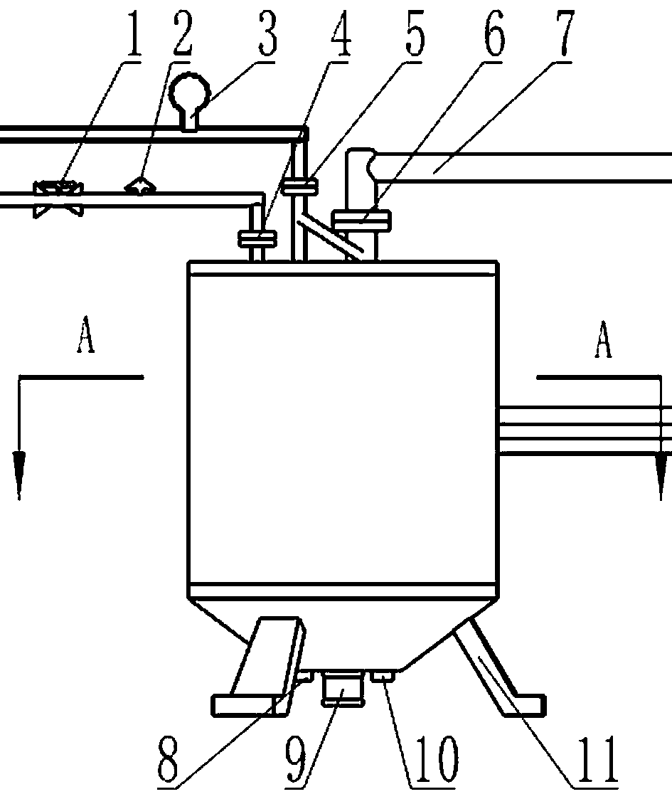
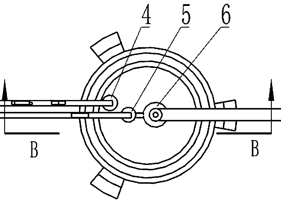
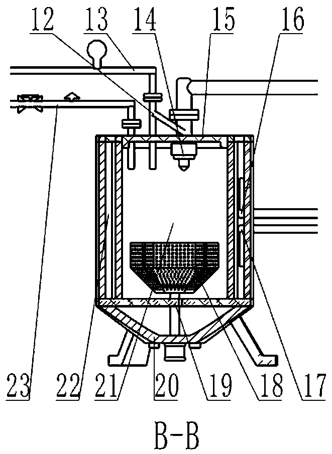
[0029] Such as figure 1 , 2 , 3, and 4, the composite functional cavity mechanism suitable for metal 3D printing post-processing of the present invention includes a ring-shaped wall cavity 21, a cover 15 on the top, a filter plate 19 and a funnel 20 on the bottom The barrel, and the heating part, the air pressure input part, the sandblasting part and the non-destructive clamping part; the heating part includes a heater 16 installed in the ring clamp wall cavity 21 and a thermocouple 17 installed in the inner cavity 22 of the barrel The air pressure input part includes a pressure gauge 3 installed on the cover 15, an air guide pipe I13, and an air guide pipe II23 provided with a vent valve 1 and an overpressure release device 2; The sandblasting pipeline 7 on the body cover 15 and the nozzle 14 installed at the lower end of the sandblasting pipeline 7, and the...


PUM


Abstract

Provided is a compound functional cavity mechanism suitable for metal three-dimensional printing post-processing. The compound functional cavity mechanism comprises an annular wall-clamping cavity, acylinder, a heating part, an air pressure input part, an abrasive blasting part and a non-destructive clamping part, wherein the top of the cylinder body is provided with a cover body, and the bottomof the cylinder body is provided with a filtering plate and a hopper; the heating part comprises a heater arranged in the annular wall-clamping cavity and a thermocouple arranged in the inner cavity of the cylinder body, the air pressure input part comprises an air duct I provided with a pressure gage and an air duct II provided with a vent valve and an over-pressure relief device, wherein the airduct I and the air duct II are arranged on the cover body; the abrasive blasting part comprises an abrasive blasting pipeline arranged on the cover body of the cylinder body and a shower nozzle arranged at the lower end of the abrasive blasting pipeline, and the abrasive blasting pipeline is communicated with the first air duct through a three-way pipe; the non-destructive clamping part comprisesa rotary screen arranged in the inner cavity of the cylinder body, and a driving shaft used for driving the rotary screen to move runs through the filtering plate and the hopper sequentially and vertically from top to bottom and is connected with the motor.

Description

technical field [0001] The invention relates to a multifunctional composite post-processing mechanism for metal 3D printing, which belongs to the technical field of post-processing of metal 3D printing parts. Background technique [0002] The principle of 3D printing technology for metal parts is to melt and accumulate metal powder or wire synchronously according to the set path under heating conditions such as laser or electron beam, and finally accumulate the three-dimensional model of complex structure layer by layer to prepare solid parts. Due to the short and rapid heating of the high-energy beam during the metal 3D printing forming process, and the rapid cooling of the metal powder after melting, coupled with poor wettability between layers, uneven heat conduction, and surface tension caused The spheroidization effect leads to low relative density, high porosity, and insufficient strength and hardness of metal 3D printed parts, which is a severe challenge for the produ...

Claims


Application Information

Patent Timeline
IPC IPC(8): B22F3/24B22F3/105B33Y40/00
CPCB22F3/24B33Y40/00B22F2003/247B22F2003/248B22F10/00B22F10/66B22F10/20B22F10/64Y02P10/25
Inventor 肖志玲闫昱丞张文杰陈亮陈冰瀛罗家艺巨智超
Owner ZHENGZHOU UNIVERSITY OF LIGHT INDUSTRY
Why Eureka
Try Eureka