Short-focus lens of projection system
A technology of projection system and focal lens, which is applied in the field of short-focus lens, can solve the problems of low throw ratio and easy scratch of aspheric lens, and achieve the effect of optimizing aberration
- Summary
- Abstract
- Description
- Claims
- Application Information
AI Technical Summary
Problems solved by technology
Method used
Image
Examples
no. 1 example
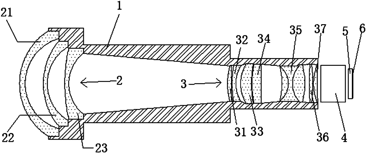
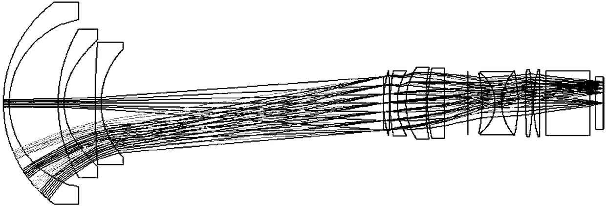
[0019] Such as figure 1 As shown, the short-focus lens of the projection system of the present invention includes a lens barrel 1, a lens front group 2 arranged on the front side of the lens barrel 1, and a lens rear group 3 arranged on the rear side of the lens barrel 1. Group 2 sequentially includes a first optical objective lens 21, an aspheric lens 22, and a second optical objective lens 23 from front to back, and the rear lens group 3 includes a third optical objective lens 31, a fourth optical objective lens 32, and a fifth optical objective lens from front to back. The objective lens 33, the sixth optical objective lens 34, the glue objective lens 35, the seventh optical objective lens 36, and the eighth optical objective lens 37. The glue objective lens 34 includes three optical objective lenses, and all the above optical objective lenses are spherical lenses. That is, the short-focus lens corresponding to the projection system of the present invention is provided with...
no. 2 example
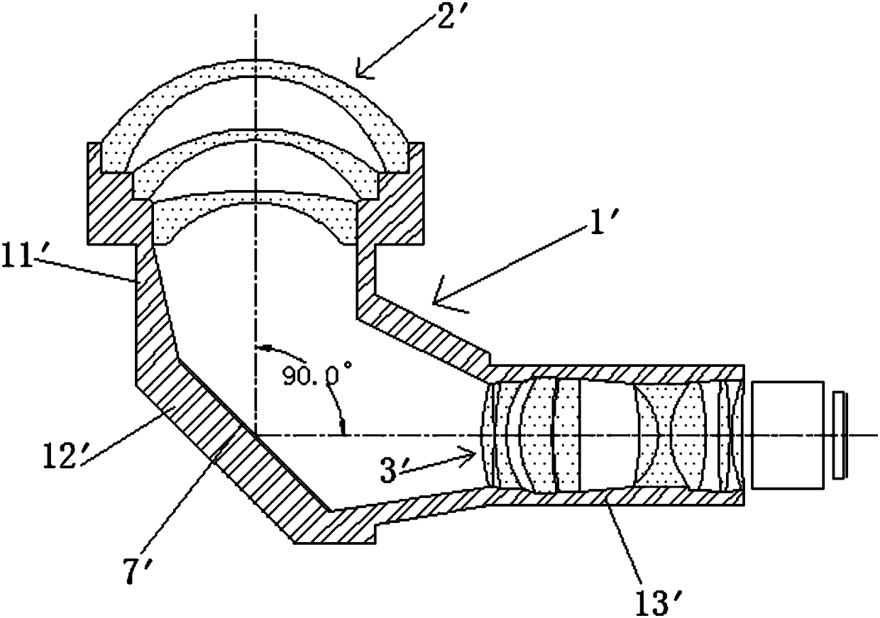
[0026] Such as image 3 As shown, in this embodiment, the lens barrel 1' includes an integrally formed front lens barrel 11', a middle lens barrel 12' and a rear lens barrel 13', and the lens front group 2' is arranged on the front lens On the barrel 11', the lens rear group 3' is arranged on the rear lens barrel 13'; the center line of the middle lens barrel 12' is not on the same straight line as the center line of the front lens barrel 11'. An included angle is formed between them, and an included angle is also formed between the centerline of the middle lens barrel 12' and the centerline of the rear lens barrel 13', and the included angles are all less than 180 degrees; the middle lens barrel 12' A reflective mirror 7' is arranged on the inner end surface of the lower side.
[0027] The centerline of the lens rear group 3' is on the same straight line as the centerlines of the prism 4' and the DMD packaging glass 5'.
[0028] The light projected from the DMD chip 6' will...
no. 3 example
[0031] Such as Figure 5 As shown, same as the second embodiment, in this embodiment, the lens barrel 1' also includes an integrally formed front lens barrel 11', a middle lens barrel 12' and a rear lens barrel 13', and the lens front group 2 'is arranged on the front lens barrel 11', and the rear lens group 3' is arranged on the rear lens barrel 13'; the center line of the middle lens barrel 12' is connected with the center of the front lens barrel 11' The lines are not on the same straight line, and an angle is formed between the two, and an angle is also formed between the centerline of the middle lens barrel 12' and the centerline of the rear lens barrel 13', and the angles are all less than 180 degrees; A reflective mirror 7' is arranged on the lower inner end surface of the middle lens barrel 12'.
[0032] The centerline of the lens rear group 3' is on the same straight line as the centerlines of the prism 4' and the DMD packaging glass 5'.
[0033] The light projected...
PUM
 Abstract
Description
Claims
Application Information
 - R&D
- Intellectual Property
- Life Sciences
- Materials
- Tech Scout
- Unparalleled Data Quality
- Higher Quality Content
- 60% Fewer Hallucinations
Browse by: Latest US Patents, China's latest patents, Technical Efficacy Thesaurus, Application Domain, Technology Topic, Popular Technical Reports.
© 2025 PatSnap. All rights reserved.Legal|Privacy policy|Modern Slavery Act Transparency Statement|Sitemap|About US| Contact US: help@patsnap.com


