Check patentability & draft patents in minutes with Patsnap Eureka AI!

Method and system for regulating engine water injection

A technology of engine and water injection, applied in the direction of engine components, engine operation, engine control, etc.

Active Publication Date: 2021-09-10
FORD GLOBAL TECH LLC
View PDF7 Cites 0 Cited by
  • Summary
  • Abstract
  • Description
  • Claims
  • Application Information

AI Technical Summary

Problems solved by technology

As a result, the desired benefits of water injection may not be provided to the engine

Method used


Image

  • Method and system for regulating engine water injection
  • Method and system for regulating engine water injection
  • Method and system for regulating engine water injection

Examples


Embodiment Construction

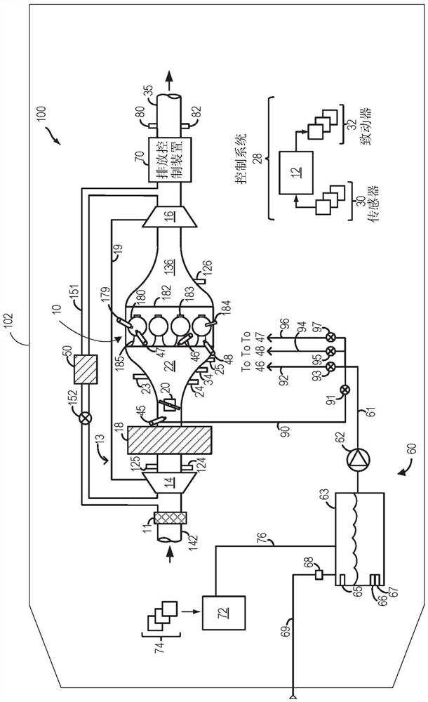
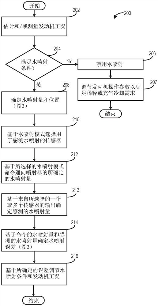
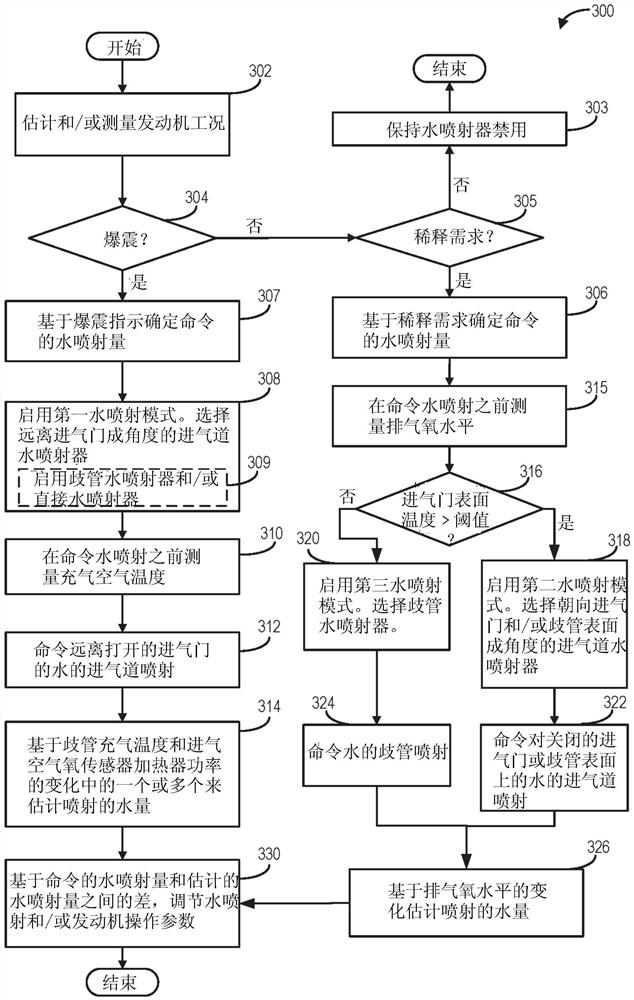
[0016] The following description relates to systems and methods for injecting water at selected locations in an engine based on engine operating conditions and adjusting water injection parameters and engine operating parameters based on measured water injection errors. figure 1 A schematic diagram of an example vehicle system including a water injection system is shown in . The water injectors may be located in the engine intake manifold, in the intake ports of the engine cylinders oriented toward the intake valves, in the intake ports oriented away from the intake valves, and / or directly coupled to each individual cylinder. The engine controller can be configured to execute control programs such as Figure 2 to Figure 3 An example routine for selecting one or more water injection locations based on engine operating conditions to provide charge air cooling, engine component cooling, and / or engine dilution benefits. Controllers can refer to things like Figure 5 A map of an ...


PUM


Abstract

The present invention relates to methods and systems for regulating engine water injection. Methods and systems are provided for injecting water into an engine and adjusting engine operation based on engine dilution requirements and engine knock. In one example, a method includes injecting water into an intake manifold via a port water injector or a manifold water injector and regulating engine operation. Additionally, the method includes adjusting engine operation based on changes in engine dilution or knock.

Description

technical field [0001] The present invention generally relates to methods and systems for injecting water at an engine based on the dilution and cooling requirements of the engine. Background technique [0002] Internal combustion engines may include a water injection system that injects water from a tank into a number of locations, including the intake manifold upstream of the engine cylinders, or injects water from the tank directly into the engine cylinders. Injecting water into the engine intake increases fuel economy and engine performance, and reduces engine emissions. When water is injected into the engine intake or cylinders, heat is transferred from the intake air and / or engine components to the water. This heat transfer leads to evaporation, which leads to cooling. Injecting water into the intake air (eg, in the intake manifold, intake ports, etc.) reduces intake air temperature and combustion temperature at the engine cylinders. By cooling the intake charge, th...

Claims


Application Information

Patent Timeline
Patent Type & Authority Patents(China)
IPC IPC(8): F02D43/00F02B47/02F02M25/028F02M25/03
CPCF02B47/02F02D35/027F02D37/02F02D41/0025F02D41/0077F02D41/1454F02M25/0227F02M25/028F02M25/03F02D2200/101F02D2200/0406F02D2200/0414F02D2200/0418F02D41/144F02D41/1494F02M25/0221F02M26/14F02M26/20F02D19/12F02M35/10222F02M35/104F01N13/10F02D41/0052
Inventor M·麦奎林D·A·马克莱德M·哈基姆G·苏尼拉
Owner FORD GLOBAL TECH LLC
Features
  • R&D
  • Intellectual Property
  • Life Sciences
  • Materials
  • Tech Scout
  • Unparalleled Data Quality
  • Higher Quality Content
  • 60% Fewer Hallucinations
Learn More