Small laser carving machine

A laser engraving machine, a small-scale technology, applied in the field of engraving, can solve the problems of inconvenient carrying, occupying a large space, etc., and achieve the effect of easy carrying, small space occupation and convenient use

Active Publication Date: 2018-06-29
苏州市相城区黄桥工业园经济发展有限公司
View PDF7 Cites 0 Cited by
  • Summary
  • Abstract
  • Description
  • Claims
  • Application Information

AI Technical Summary

Problems solved by technology

[0003] The above-mentioned laser engraving machine takes

Method used


Image

  • Small laser carving machine
  • Small laser carving machine
  • Small laser carving machine

Examples


Example Embodiment

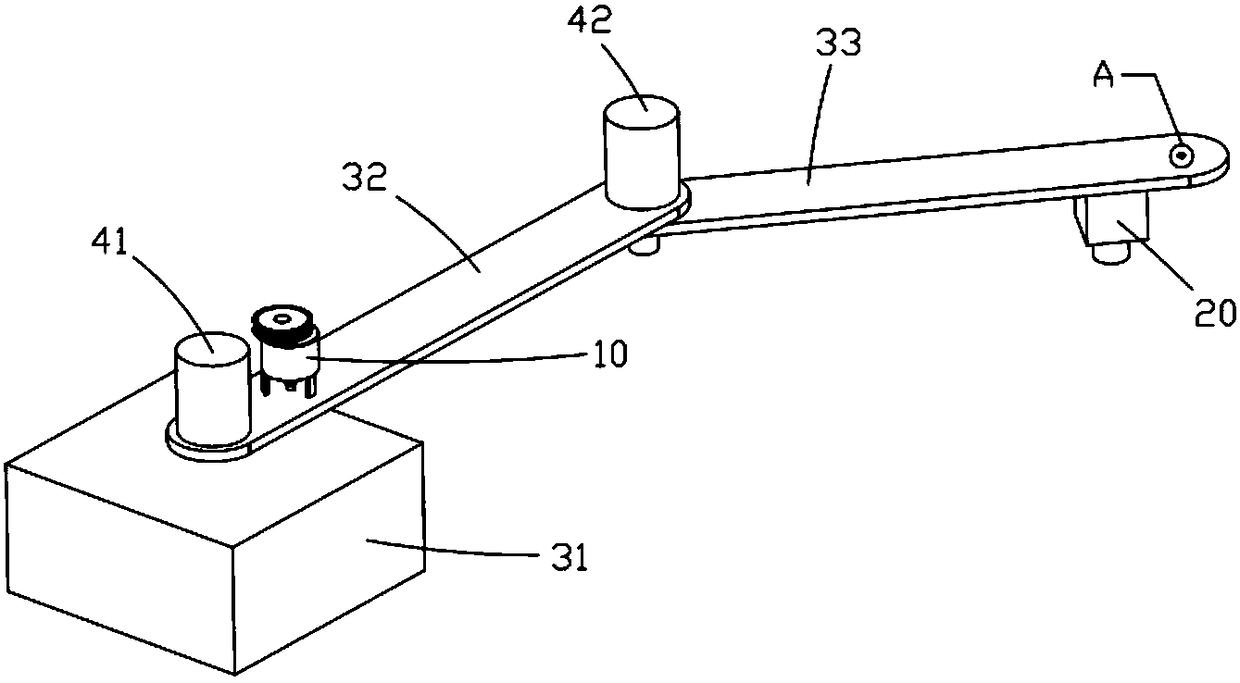
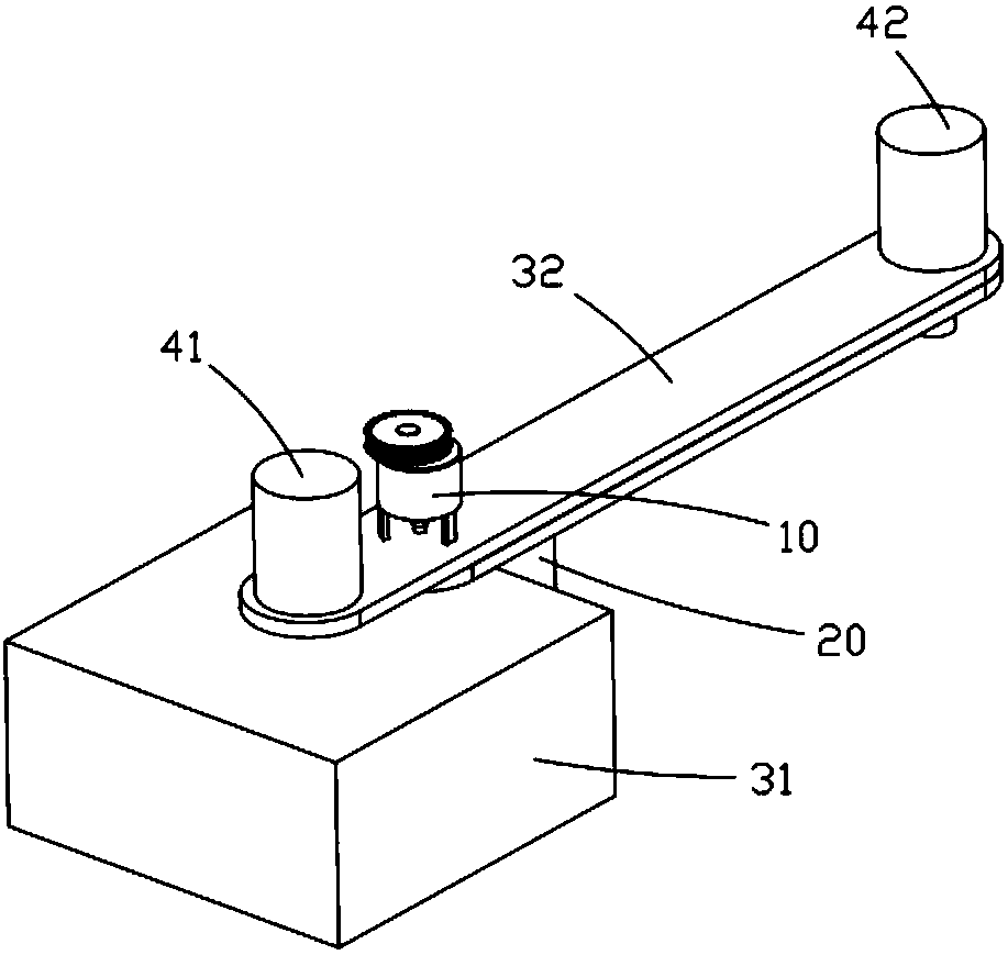
[0024] A small laser engraving machine includes a laser 20 and a driving system for driving the displacement of the laser.

[0025] Combine figure 1 , figure 2 The driving system includes a base 31, a large arm 32, and a small arm 33. The large arm is pivotally connected to the base, the small arm is pivotally connected to the large arm, and the laser is mounted on the small arm. A servo motor 41 drives the big arm to rotate around the base, and a second servo motor 42 drives the small arm to rotate around the big arm. Wherein, the small arm 33 is located below the big arm 32, and the laser 20 is located below the small arm, so that the big arm and the small arm can be stacked up and down for storage.

[0026] The boom 32 is pivotally connected to the base 31 via a first shaft, the small arm 33 is pivotally connected to the boom via a second shaft, the first servo motor 41 is mounted on the boom, and the first servo motor Connected to the first shaft, the second servo motor 42 is...


PUM


Abstract

A small laser carving machine comprises a laser device and a drive system for driving the laser device to move. The drive system comprises a base, a big arm and a small arm. The big arm is in pivot joint to the base, the small arm is in pivot joint to the big arm, and the laser device is arranged on the small arm. A first servo motor drives the big arm to rotate around the base, and a second servomotor drives the small arm to rotate around the big arm. During storage, the big arm and the small arm are overlapped up and down and locked to the base through a lock, accordingly, the occupied space of the carving machine is reduced, and carrying is convenient.

Description

technical field [0001] The invention relates to the technical field of engraving, in particular to engraving equipment. Background technique [0002] The patent document with the application number 201710587608.2 discloses a laser engraving machine with a new structure, including a Y-axis guide rail, an X-axis cantilever mounted on the Y-axis guide rail, and a laser located on the X-axis cantilever. Driven by the motor, the laser can Slide along the X-axis cantilever and Y-axis guide rail. [0003] The above-mentioned laser engraving machine takes up a large space when it is stored and is inconvenient to carry. Contents of the invention [0004] The technical problem solved by the invention: the laser engraving machine takes up little space when stored and is easy to carry. [0005] In order to solve the above technical problems, the present invention provides the following technical solutions: a small laser engraving machine, including a laser and a drive system for dri...

Claims


Application Information

Patent Timeline
IPC IPC(8): B23K26/08B23K26/362
CPCB23K26/0876B23K26/361
Inventor 陈玉燕
Owner 苏州市相城区黄桥工业园经济发展有限公司
Why Eureka
Try Eureka