Well drilling equipment for petroleum exploitation

A technology for drilling and equipment, which is applied in the field of drilling equipment for oil development, which can solve the problems of complex operation, low drilling efficiency, and dust that cannot be treated, and achieve the effects of simple operation, high drilling efficiency, and dust treatment

Inactive Publication Date: 2018-06-29
魏文福
View PDF5 Cites 15 Cited by
  • Summary
  • Abstract
  • Description
  • Claims
  • Application Information

AI Technical Summary

Problems solved by technology

[0006] In order to overcome the shortcomings of the existing drilling equipment such as low drilling efficiency, complicated operation, and dust that cannot be treated during drilling, the technical problem

Method used


Image

  • Well drilling equipment for petroleum exploitation
  • Well drilling equipment for petroleum exploitation
  • Well drilling equipment for petroleum exploitation

Examples


Example Embodiment

[0027] Example 1

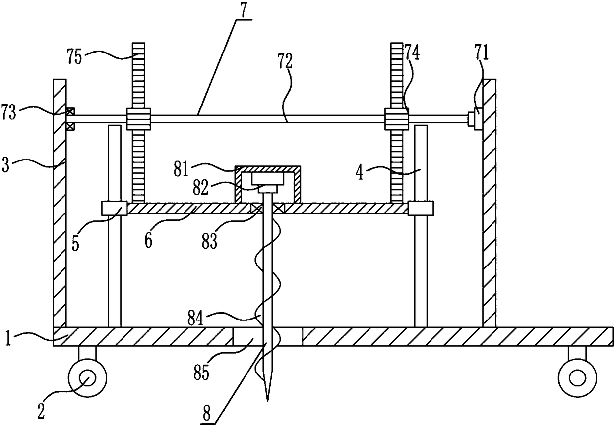
[0028] A kind of oil exploitation uses drilling equipment, such as Figure 1-3 As shown, it includes a bottom plate 1, a wheel 2, a vertical plate 3, a guide rod 4, a guide sleeve 5, a fixed plate 6, a lifting mechanism 7 and a drilling mechanism 8. The bottom of the bottom plate 1 is provided with wheels 2, and the top of the bottom plate 1 is provided with wheels 2 on the left and right sides. The vertical plate 3, a lifting mechanism 7 is arranged on the upper part between the left and right vertical plates 3, the left and right vertical plates 3 are provided with guide rods 4 symmetrically on the left and right sides, the guide rod 4 is provided with a guide sleeve 5, and the left and right two guide sleeves 5 A fixed plate 6 is connected therebetween, and a drilling mechanism 8 is arranged in the middle of the fixed plate 6 .

Example Embodiment

[0029] Example 2

[0030] A kind of oil exploitation uses drilling equipment, such as Figure 1-3 As shown, it includes a bottom plate 1, a wheel 2, a vertical plate 3, a guide rod 4, a guide sleeve 5, a fixed plate 6, a lifting mechanism 7 and a drilling mechanism 8. The bottom of the bottom plate 1 is provided with wheels 2, and the top of the bottom plate 1 is provided with wheels 2 on the left and right sides. The vertical plate 3, a lifting mechanism 7 is arranged on the upper part between the left and right vertical plates 3, the left and right vertical plates 3 are provided with guide rods 4 symmetrically on the left and right sides, the guide rod 4 is provided with a guide sleeve 5, and the left and right two guide sleeves 5 A fixed plate 6 is connected therebetween, and a drilling mechanism 8 is arranged in the middle of the fixed plate 6 .

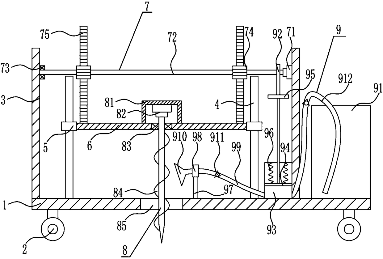
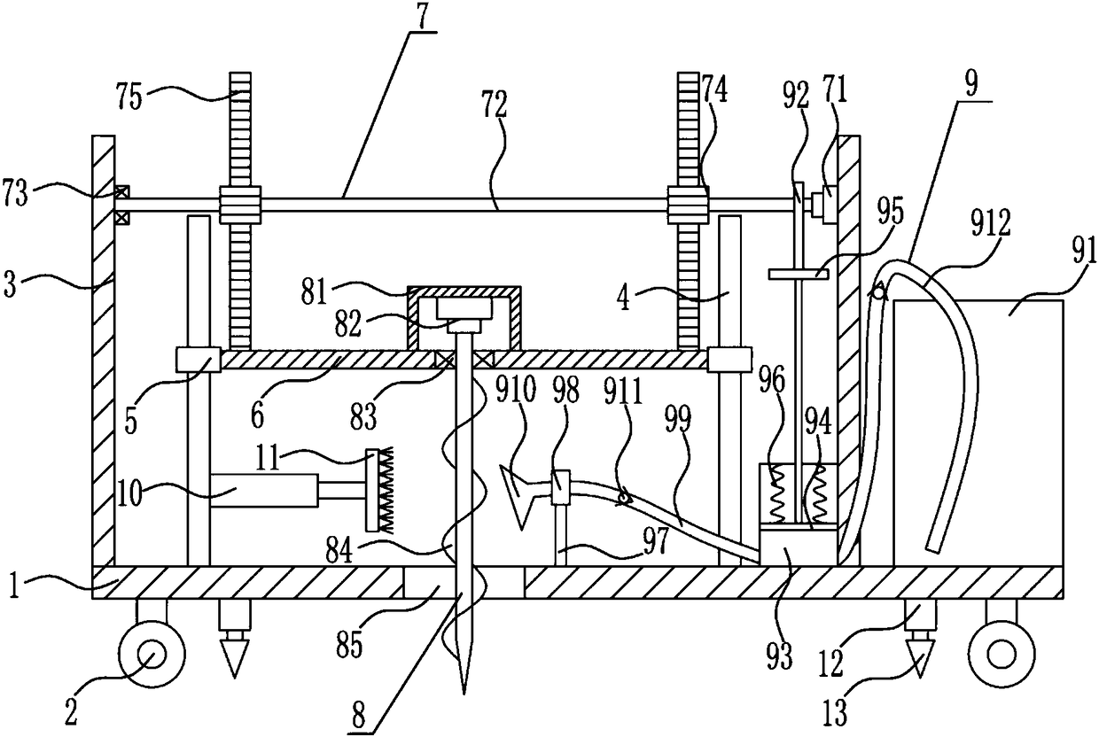
[0031] The lifting mechanism 7 includes a first motor 71 , a rotating shaft 72 , a first bearing seat 73 , a gear 74 and a rac...

Example Embodiment

[0032] Example 3

[0033] A kind of oil exploitation uses drilling equipment, such as Figure 1-3 As shown, it includes a bottom plate 1, a wheel 2, a vertical plate 3, a guide rod 4, a guide sleeve 5, a fixed plate 6, a lifting mechanism 7 and a drilling mechanism 8. The bottom of the bottom plate 1 is provided with wheels 2, and the top of the bottom plate 1 is provided with wheels 2 on the left and right sides. On the vertical plate 3, a lifting mechanism 7 is arranged on the upper part between the left and right vertical plates 3, and a guide rod 4 is symmetrically arranged on the inner side of the left and right vertical plates 3. The guide rod 4 is provided with a guide sleeve 5, and the left and right guide sleeves 5 A fixed plate 6 is connected therebetween, and a drilling mechanism 8 is arranged in the middle of the fixed plate 6 .

[0034]The lifting mechanism 7 includes a first motor 71 , a rotating shaft 72 , a first bearing seat 73 , a gear 74 and a rack 75 , the...


PUM


Abstract

The invention relates to well drilling equipment, in particular to well drilling equipment for petroleum exploitation. According to the well drilling equipment for petroleum exploitation, the well drilling efficiency is high, operation is easy, dust can be treated in well drilling. The well drilling equipment for petroleum exploitation comprises a bottom plate and the like, wheels are arranged atthe bottom of the bottom plate, vertical plates are arranged on the left portion and the right portion of the top of the bottom plate correspondingly, and a lifting mechanism is arranged on the upperportion between the left vertical plate and the right vertical plate. Guiding rods are symmetrically arranged on the inner sides of the left vertical plate and the right vertical plate in the left-right direction, guiding sleeves are arranged on the guiding rods, and a fixing plate is connected between the left guiding sleeve and the right guiding sleeve. A well drilling mechanism is arranged in the middle of the fixing plate. According to the well drilling equipment for petroleum exploitation, through cooperation of the lifting mechanism and the well drilling mechanism, well drilling is downwards conducted, the well drilling speed is high, dust falling treatment can be conducted on the surrounding environment through a dust falling mechanism, the and the effects that the well drilling efficiency is high, operation is easy, and the dust can be treated in well drilling are achieved.

Description

technical field [0001] The invention relates to a drilling equipment, in particular to a drilling equipment for oil exploitation. Background technique [0002] Oil extraction refers to the act of digging and extracting oil in places where oil is stored. In the process of oil extraction, oil and gas flow from the reservoir to the bottom of the well, and then rise from the bottom of the well to the wellhead. [0003] Drilling engineering plays a very important role in the development of oil and gas fields. In the construction of an oil and gas field, drilling engineering often accounts for more than 50% of the total investment. The development of an oil and gas field often requires drilling hundreds or even thousands or more wells. There are different technical requirements for wells used for different purposes such as production, observation and control (such as production wells, injection wells, observation wells, and inspection wells for checking the effect of water washi...

Claims


Application Information

Patent Timeline
IPC IPC(8): E21B7/02E21B15/00E21B21/00E21B12/00
CPCE21B7/02E21B12/00E21B15/003E21B21/00
Inventor 魏文福周丛然劳国豪
Owner 魏文福
Why Eureka
Try Eureka