Improved dust remover device

A dust collector and improved technology, applied in coupling devices, parts of connecting devices, devices preventing contact with live contacts, etc., can solve problems such as electric shock accidents, potential safety hazards, and exposed sockets, and reduce electric shocks. The effect of accidents, safe and stable operation, and cost reduction

Inactive Publication Date: 2018-06-29
桐乡市卡顿商贸有限公司
View PDF0 Cites 0 Cited by
  • Summary
  • Abstract
  • Description
  • Claims
  • Application Information

AI Technical Summary

Problems solved by technology

[0002] Nowadays, when the dust collector is energized, the plug connected to it is directly inserted into the slot of the power transmission base, and the slot of the power transmission base is always connected to the mains. When the dust collector i

Method used


Image

  • Improved dust remover device
  • Improved dust remover device
  • Improved dust remover device

Examples


Example Embodiment

[0020] The preferred embodiments of the present invention will be described in detail below with reference to the accompanying drawings, so that the advantages and features of the present invention can be more easily understood by those skilled in the art, so that the protection scope of the present invention can be more clearly defined.

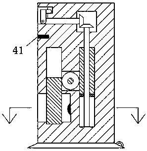
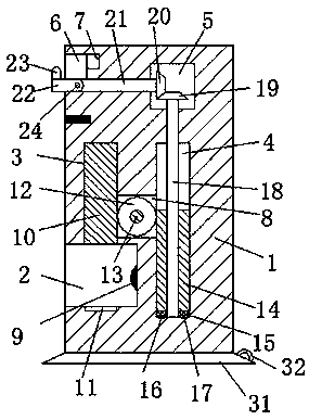
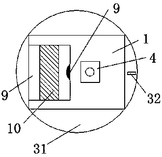
[0021] See Figure 1-3 An improved dust collector device shown includes a power transmission base 1, a suction cup 31 is fixedly mounted on the bottom end of the power transmission base 1, and a pull ring 32 is fixedly mounted on the upper right side of the suction cup 31. The pull ring 32 is used to release the suction force of the suction cup 31, a slot 2 is provided on the left end of the power transmission base 1, a contact pin 9 is provided on the right end wall of the slot 2, and a contact pin 9 is provided on the top wall of the slot 2 The first chute 3 connected to the slot 2 is provided with a second chute 4 that expands up and down an...


PUM


Abstract

The invention discloses an improved dust remover device, which comprises a power transmission base. A suction cup is fixedly installed on the bottom end surface of the power transmission base. A pullring is fixedly installed on upper part of the right side surface of the suction cup. An insertion slot is formed in the left end surface of the power transmission base. A contact pin is arranged on the right end wall of the insertion slot. A first sliding slot communicated with the insertion slot is formed in the top end wall of the insertion slot. A second sliding slot extending vertically and parallel to the first sliding slot is formed in the power transmission base and positioned at the right end of the insertion slot. A locking slot opposite to the first sliding slot is formed in the bottom end wall of the insertion slot. An operation cavity is formed in the left end surface of the power transmission base and positioned above the insertion slot. An accommodating slot is formed in theright end wall of the operation cavity. A first rotating cavity is formed in the power transmission base and positioned above the second sliding slot. The improved dust remover device is simple in overall structure, and effectively reduces the occurrence of electric shock accidents in the present life.

Description

technical field [0001] The invention relates to the field of dust collectors, in particular to an improved dust collector device. Background technique [0002] Nowadays, when the dust collector is energized, the plug connected to it is directly inserted into the slot of the power transmission base, and the slot of the power transmission base is always connected to the mains. When the dust collector is not in use, the plug It is often pulled out from the slot, which will cause the exposure of the slot. Because no protective parts are set outside the slot, it will easily cause electric shock accidents, and there is a greater potential safety hazard. Contents of the invention [0003] The technical problem to be solved by the present invention is to provide an improved dust collector device, which can solve the above-mentioned problems in the prior art. [0004] In order to solve the above problems, the present invention adopts the following technical solution: An improved d...

Claims


Application Information

Patent Timeline
IPC IPC(8): H01R13/44H01R13/629
CPCH01R13/44H01R13/629
Inventor 汪任斌
Owner 桐乡市卡顿商贸有限公司
Why Eureka
Try Eureka