Supercharge Your Innovation With Domain-Expert AI Agents!

A device for removing iron scraps by cooling cutting fluid for machining iron products

A technology for machining and cutting fluid, applied in solid separation, chemical instruments and methods, magnetic separation, etc., can solve problems such as inconvenient discharge, perishable filter screen, waste of coolant, etc.

Active Publication Date: 2019-08-06
上海正如金属制品有限公司
View PDF8 Cites 0 Cited by
  • Summary
  • Abstract
  • Description
  • Claims
  • Application Information

AI Technical Summary

Problems solved by technology

[0002] In the process of cutting iron workpieces, some equipment needs to use a large amount of processing coolant in order to make the cutting process more efficient and smooth. The coolant will be mixed with the iron filings generated during processing. The traditional device is generally The coolant and iron filings are directly collected in a container, but in the process of processing large workpieces, a large amount of coolant will be generated, resulting in more waste of coolant. The existing device generally uses a filter to collect the coolant. The broken iron chips in the filter can make the coolant recycle, but the filtering effect of the general filter device is not good, and the broken iron chips are easy to get stuck on the filter screen, which is inconvenient to discharge, and the filter screen is easy to rot

Method used


Image

  • A device for removing iron scraps by cooling cutting fluid for machining iron products
  • A device for removing iron scraps by cooling cutting fluid for machining iron products
  • A device for removing iron scraps by cooling cutting fluid for machining iron products

Examples


Embodiment Construction

[0016] The following will clearly and completely describe the technical solutions in the embodiments of the present invention with reference to the accompanying drawings in the embodiments of the present invention. Obviously, the described embodiments are only some, not all, embodiments of the present invention. Based on the embodiments of the present invention, all other embodiments obtained by persons of ordinary skill in the art without making creative efforts belong to the protection scope of the present invention.

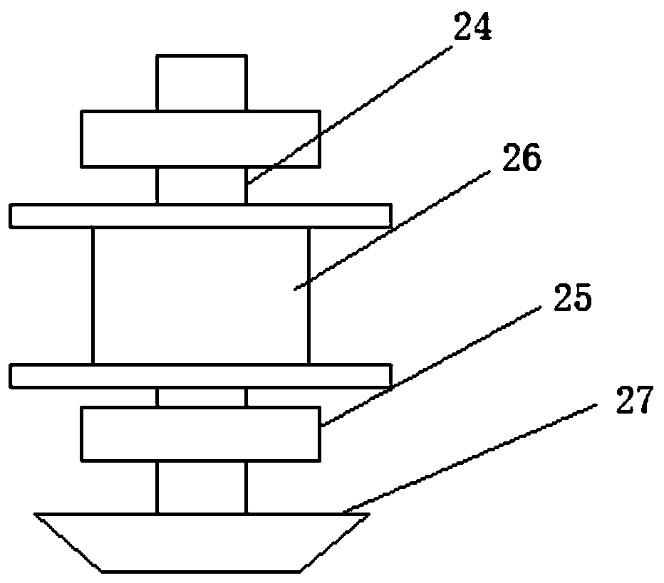
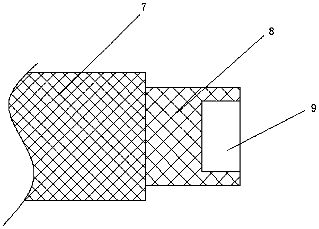
[0017] see Figure 1~3 , in an embodiment of the present invention, a cooling and cutting fluid chip removal device for machining iron products, comprising a chip removal box 1 and a base plate 2, the bottom of the chip removal box 1 is fixed on the base by a plurality of support columns 3 On the board 2, liquid inlets 4 are provided on both sides of the top wall of the chip removal box 1, and a discharge port 5 is provided on the bottom side wall of the chip ...


PUM


Abstract

The invention discloses a cooling cutting liquid scrap iron removing device for ironwork machining. The device comprises a scrap removing box and a base plate, a cavity is formed in a first retainingplate, a second retaining plate is arranged in the cavity, the outer end of the second retaining plate is hinged to the inner side wall of the scrap removing box, a lifting vertical shaft coaxial witha pipe barrel is arranged in the pipe barrel, a lifting auger is arranged on the lifting vertical shaft, a through hole is formed in the joint of the pipe barrel and the bottom wall of the scrap moving box, drainage plates are arranged on the side wall of the top of the pipe barrel and the upper side wall of the lifting vertical shaft, an electromagnet is embedded in the side wall of the scrap removing box, a transmission cross shaft is arranged between two support columns, and the transmission cross shaft is connected with the bottom of the pipe barrel through a forward and reverse transmission mechanism. Accordingly, the structure is simple, scrap iron in cutting liquid can be circulated, filtered and removed, the removing effect is good, the phenomenon that the cutting liquid is reused, and the scrap iron disturbs machining is avoided, the scrap iron in the scrap removing box is discharged conveniently, operation is easy and rapid, and the practicability is high.

Description

technical field [0001] The invention relates to a mechanical device, in particular to a cooling and cutting fluid iron chip removal device for machining iron products. Background technique [0002] In the process of cutting iron workpieces, some equipment needs to use a large amount of processing coolant in order to make the cutting process more efficient and smooth. The coolant will be mixed with the iron filings generated during processing. The traditional device is generally The coolant and iron filings are directly collected in a container, but in the process of processing large workpieces, a large amount of coolant will be generated, resulting in more waste of coolant. The existing device generally uses a filter to collect the coolant. The broken iron chips in the filter can make the coolant recycle, but the filtering effect of the general filter device is not good, and the broken iron chips are easy to get stuck on the filter screen, which is inconvenient to discharge,...

Claims


Application Information

Patent Timeline
Patent Type & Authority Patents(China)
IPC IPC(8): B03C1/30B03C1/14
CPCB03C1/14B03C1/30
Inventor 李绩
Owner 上海正如金属制品有限公司
Features
  • R&D
  • Intellectual Property
  • Life Sciences
  • Materials
  • Tech Scout
  • Unparalleled Data Quality
  • Higher Quality Content
  • 60% Fewer Hallucinations
Learn More