Automatic welding device for main girder web reinforcing steel of crane

A main girder web and automatic welding technology, applied in auxiliary devices, welding accessories, welding equipment, etc., can solve the problems of narrow space, increased cost, low production efficiency, etc., achieve a high degree of automation, prevent web deformation, and weld fast effect

Pending Publication Date: 2018-07-10
SHANQI HEAVY MACHINERY
View PDF0 Cites 1 Cited by
  • Summary
  • Abstract
  • Description
  • Claims
  • Application Information

AI Technical Summary

Problems solved by technology

However, due to the narrow space, the smoke generated by welding is not easy to spread, causing serious harm to the health of wel

Method used


Image

  • Automatic welding device for main girder web reinforcing steel of crane
  • Automatic welding device for main girder web reinforcing steel of crane
  • Automatic welding device for main girder web reinforcing steel of crane

Examples


Embodiment Construction

[0035] In order to make the object, technical solution and advantages of the present invention clearer, the present invention will be further described in detail below in conjunction with the accompanying drawings and embodiments. It should be understood that the specific embodiments described here are only used to explain the present invention and not to limit the present invention.

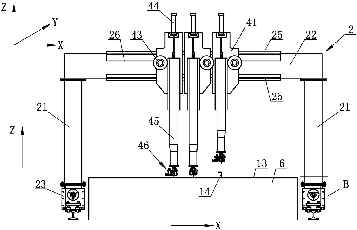
[0036] Define the XYZ coordinate system as image 3 shown.

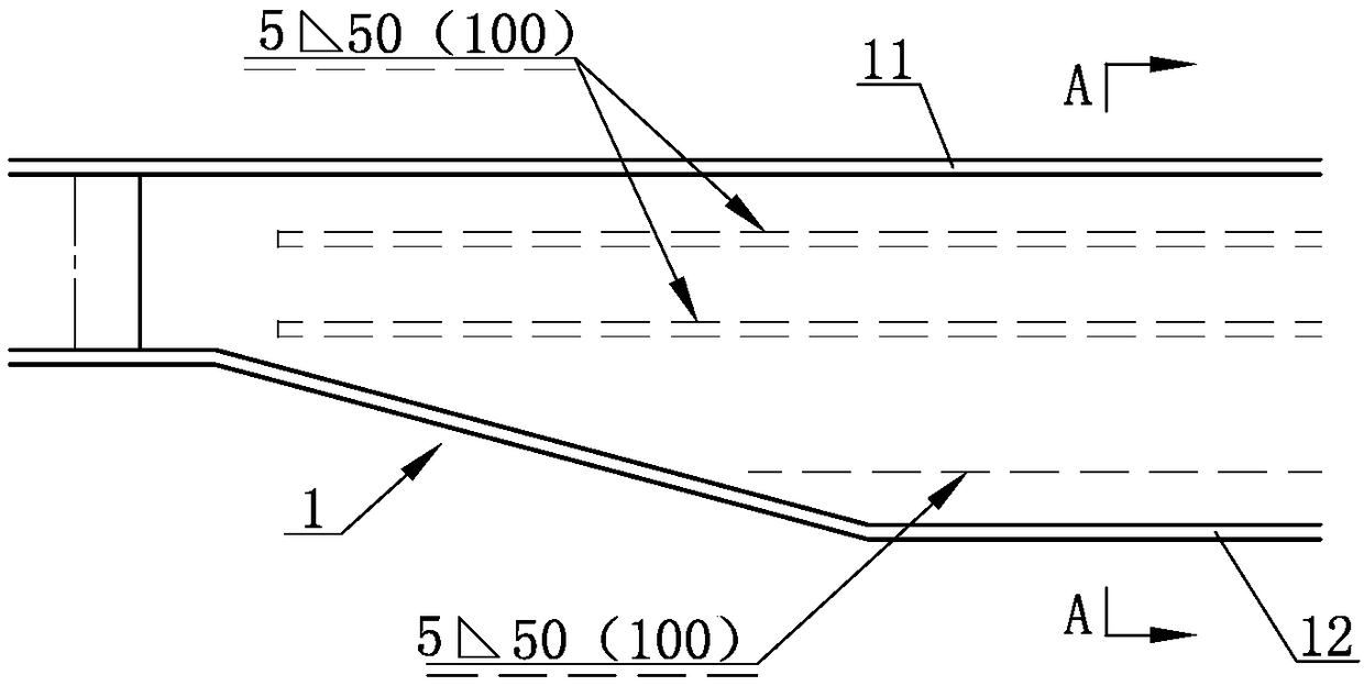
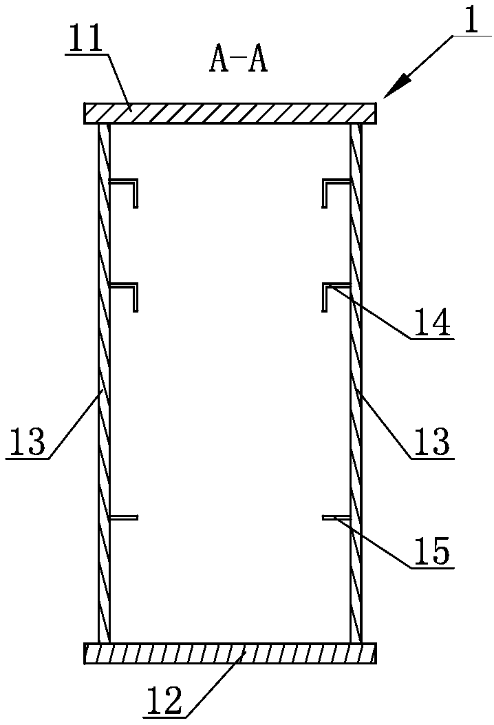
[0037] Such as image 3 , Figure 4 and Figure 5 Commonly shown, an automatic welding device for crane main girder web reinforcement steel, a Π-shaped gantry 2, the gantry 2 includes two columns 21 and a beam 22 fixed on the upper ends of the two columns 21, and the lower ends of the two columns 21 They are respectively fixed on the box body 23, and the box body 23 is fixedly provided with a gantry motor and a gantry reducer driven by the gantry motor, and the output end of the gantry reducer is fixedly connected with walking roll...


PUM


Abstract

The invention discloses an automatic welding device for a main girder web reinforcing steel of a crane. The automatic welding device comprises a walking-type portal; the portal is driven by a walkingmechanism to walk along an X direction; the portal comprises two vertical posts and a cross beam which is fixedly arranged on upper ends of the two vertical post; at least one welding trolley which can move along a Y direction is arranged on the cross beam and is driven by a trolley driving device; the welding trolley is provided with a welding gun; the welding gun can move along a Z direction; the portal drives the welding gun to move along the length direction of a web; a steel angle and a steel flat are welded on the web; and meanwhile, the welding trolley drives the welding gun to move along the width direction of the web. The welding equipment is high in automation degree; and welding efficiency and welding quality are greatly improved.

Description

technical field [0001] The invention relates to the technical field of crane production equipment, in particular to an automatic welding device for crane girder web reinforcement steel. Background technique [0002] Such as figure 1 and figure 2 Commonly shown, the main girder 1 of a crane (such as a bridge crane, a gantry crane) includes two webs 13 arranged at intervals, and the upper and lower ends of the webs 13 are respectively fixedly connected with an upper flange plate 11 and a lower flange plate 12 The inner surfaces of the two webs 13 are respectively welded and fixedly connected with reinforced angle steel 14 or reinforced flat steel 15 arranged along the length direction of the webs 13 . [0003] At present, the traditional welding method is to first weld the upper flange plate 11 and the two webs 13 together to form a Π-shaped beam, and then manually weld the reinforced angle steel 14 or the reinforced flat steel 15 to the two webs 13. The inner surface. Ho...

Claims


Application Information

Patent Timeline
IPC IPC(8): B23K9/32B23K37/02
CPCB23K9/32B23K37/02
Inventor 刘永庆王丰顺房师平张磊言陈晓庆
Owner SHANQI HEAVY MACHINERY
Why Eureka
Try Eureka