Radio frequency foaming device

A foaming device and radio frequency technology, applied in the coating and other directions, can solve the problems that metal materials cannot be used, cannot be metal materials, cannot be used, etc., and achieve the effect of good radio frequency shielding and uniform heating.

Pending Publication Date: 2018-07-10
QUANZHOU NORMAL UNIV
View PDF7 Cites 2 Cited by
  • Summary
  • Abstract
  • Description
  • Claims
  • Application Information

AI Technical Summary

Problems solved by technology

However, there are technical problems in the traditional microwave heating method, that is, when using microwave heating, there are special requirements for the food container, which cannot be made of metal materials and must be able to penetrate radio frequency
In the prior art, microwave heating is used to make the polymer foam, and the mold and the polymer to be foamed in the mold are put into a microwave environment for heating and foaming. There is the same technical problem as

Method used


Image

  • Radio frequency foaming device
  • Radio frequency foaming device

Examples


Embodiment 1

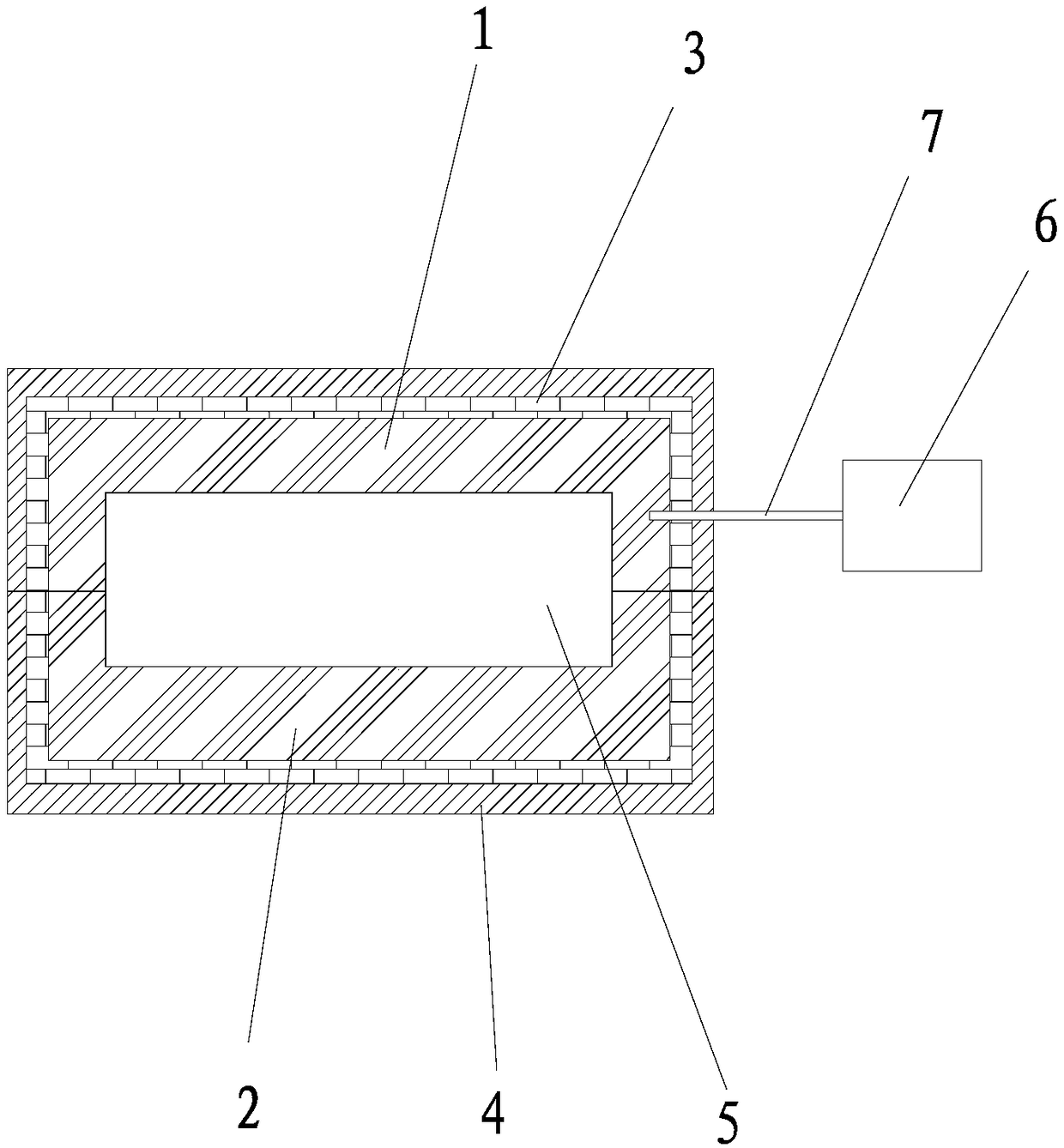
[0028] The radio frequency foaming device of the present invention is suitable for foaming use of polymer materials. Such as figure 1 As shown, the radio frequency foaming device includes a foaming mold and a solid radio frequency power source 6, and the foaming mold is electrically connected to the solid radio frequency power source 6 via a coaxial cable 7. The solid-state radio frequency power source 6 is a well-known technology. The aforementioned foaming mold includes an upper mold 1 and a lower mold 2. In this embodiment, taking the orientation of the foaming device in actual use as the reference orientation, the vertical cross-sections of the upper mold 1 and the lower mold 2 are U-shaped surfaces, respectively, the upper mold 1 has a first cavity, and the lower mold 2 With a second cavity, the U-shaped open end of the upper mold 1 and the U-shaped open end of the lower mold 2 are relatively closed together. After the molds are closed (that is, the upper mold 1 and the l...

Embodiment 2

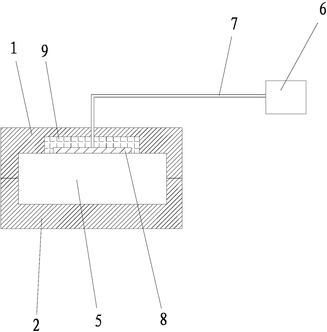
[0036] The difference between this embodiment and the first embodiment lies in: the applicable foaming material of the radio frequency foaming device of this embodiment is different from that of the first embodiment, and at the same time, there is a difference in the radio frequency generating structure of the radio frequency foaming device of this embodiment.

[0037] The radio frequency foaming device of the present invention is suitable for the foaming of PU, TPU, EVA, PE, PP, SEBS, CPE, PE, PS and other polymer materials or a variety of polymer blend materials. Polymer materials with weak properties can also be used as radio frequency absorbers by blending materials with strong polarity. For example, the molecular structure contains such as -OH, -NH 2 , -COOH and other high-polarity functional groups, or polymers that can form intramolecular or intermolecular hydrogen bonds in the molecular structure; and non-polymer chemical substances such as water molecules, alcohols, glycer...


PUM


Abstract

The invention discloses a radio frequency foaming device. The device comprises a foaming mold and a solid radio frequency power source, the solid radio frequency power source is electrically connectedwith the foaming mold or a radiation unit through a coaxial cable, and the radio frequency is sent out through the foaming mold or the radiation unit and is reflected in a mold cavity; and the temperature of to-be-foamed parent materials is gradually increased due to the fact that the wave-absorbing materials in the to-be-foamed parent materials in the mold cavity absorb the radio frequency, whenthe temperature is higher than the decomposition temperature of a foaming agent, the foaming agent rapidly decomposes and generates gas, then the foaming materials are promoted to expand until the whole mold cavity is filled, and therefore foaming of the foaming materials is realized. The foaming device can realize rapid, efficient and uniform foaming of the foaming materials. The device has a wide application prospect in the field of foaming material foaming.

Description

Technical field [0001] The invention relates to the technical field of foaming molding equipment for foamed materials, and in particular to a device for realizing foaming of foamed materials by radio frequency heating. Background technique [0002] High molecular polymer foam materials are widely used in heat insulation, sound insulation, shock absorption, shoemaking and other fields. At present, the common foaming methods of polymer materials (foaming materials) include physical foaming and chemical foaming. The chemical foaming method means that after the chemical foaming agent is blended with the polymer material, at a certain temperature, the chemical foaming agent is thermally decomposed, generates gas, expands, and foams the polymer material. The current heating method is mainly electric heating Because the electric heating process heats the polymer material through thermal conduction, that is, the foaming mold is first heated by the electric heating plate, and the foaming...

Claims


Application Information

Patent Timeline
IPC IPC(8): B29C44/34B29C44/58B29C33/56B29C33/38
CPCB29C33/38B29C33/56B29C44/3415B29C44/58
Inventor 朱君秋吴清实罗水源
Owner QUANZHOU NORMAL UNIV
Why Eureka
Try Eureka