Check patentability & draft patents in minutes with Patsnap Eureka AI!

Valve structure of shock absorber

A shock absorber and flow path technology, applied in the direction of shock absorbers, shock absorbers, springs/shock absorbers, etc., can solve the problems of ride comfort, lower pressure relief points, and traditional piston valves that do not have performance curves.

Active Publication Date: 2018-07-20
HL MANDO CORP
View PDF6 Cites 4 Cited by
  • Summary
  • Abstract
  • Description
  • Claims
  • Application Information

AI Technical Summary

Problems solved by technology

[0008] However, since conventional piston valves have a structure in which one or more flow paths are associated, conventional piston valves do not have independent performance curves
Therefore, there are many restrictions in independent tuning and free tuning, and there is a risk of pressure relief point phenomenon and reduced ride comfort in the process of opening and closing the disc

Method used


Image

  • Valve structure of shock absorber
  • Valve structure of shock absorber
  • Valve structure of shock absorber

Examples


Embodiment Construction

[0021] Hereinafter, exemplary embodiments of the present disclosure will be described in detail with reference to the accompanying drawings.

[0022] The advantages and features of the present disclosure and how to achieve them should be clearly understood with reference to the accompanying drawings and the following detailed embodiments.

[0023] However, the present disclosure is not limited to the disclosed embodiments, but may be implemented in various forms. The embodiments are provided to fully explain the present disclosure to those skilled in the art and to fully explain the scope of the present disclosure. The scope of the present disclosure is defined by the appended claims.

[0024] In addition, in describing the present invention, when it is determined that related known techniques and the like unnecessarily obscure the gist of the present invention, their detailed description will be omitted.

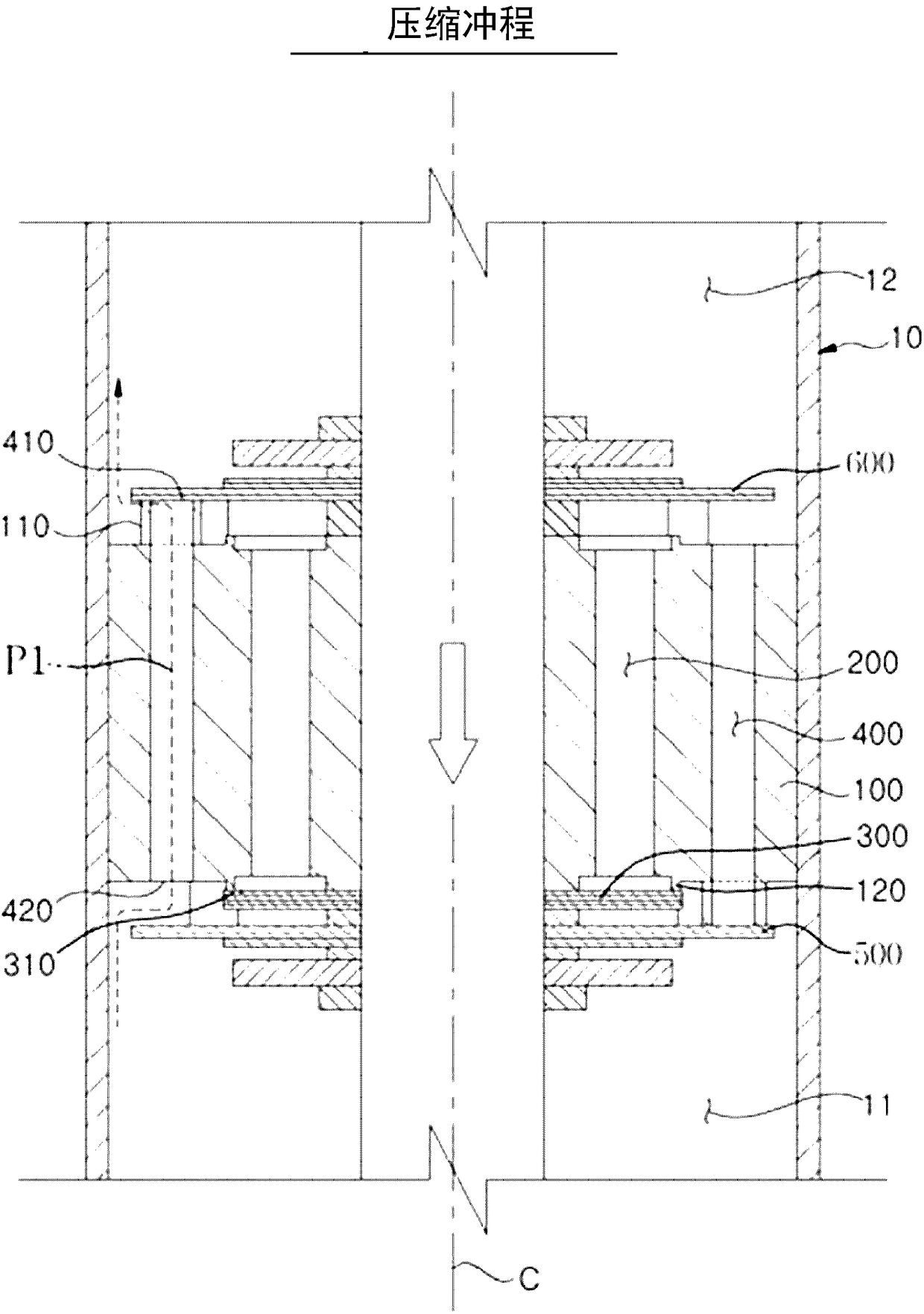
[0025] figure 1 is a sectional view showing a compression stroke of...


PUM


Abstract

The present disclosure relates to a valve structure of a shock absorber in which ride comfort degradation may be prevented by forming a first flow path and a second flow path independently formed without associating them to each other such that disks do not sequentially open and cause a blow-off phenomenon, and a degree of tuning freedom may be improved by forming the first flow path and the second flow path independently without interference.

Description

[0001] Cross References to Related Applications [0002] This application claims priority and benefit from Korean Patent Application No. 2017-0006337 filed on January 13, 2017, the disclosure of which is incorporated herein by reference in its entirety. technical field [0003] The present disclosure relates to a valve structure of a shock absorber, and more particularly, to a valve structure of a shock absorber in which a first flow path and a second flow path are individually opened due to forming independent opening and closing structures and closed so that the first flow path is not associated with the second flow path, thus preventing the blow-off phenomenon and the reduction in ride comfort due to the blow-off phenomenon, and due to the first flow path and the second flow Paths are formed independently without interference, so the degree of freedom in tuning increases. Background technique [0004] Generally, a shock absorber absorbs and releases vertical vibration en...

Claims


Application Information

Patent Timeline
Patent Type & Authority Applications(China)
IPC IPC(8): F16F9/34F16F9/32
CPCF16F9/3207F16F9/34F16F9/3485F16F9/3405F16F9/325F16F9/3484
Inventor 金南昊
Owner HL MANDO CORP
Features
  • R&D
  • Intellectual Property
  • Life Sciences
  • Materials
  • Tech Scout
  • Unparalleled Data Quality
  • Higher Quality Content
  • 60% Fewer Hallucinations
Learn More