A new energy vehicle transmission device
A new energy vehicle and transmission technology, applied in the field of automobile transmission, can solve problems such as the decline in the quality of lubricating oil, failure to protect the gear set, and affecting the quality of lubricating oil.
- Summary
- Abstract
- Description
- Claims
- Application Information
AI Technical Summary
Problems solved by technology
Method used
Image


Examples
Embodiment 1
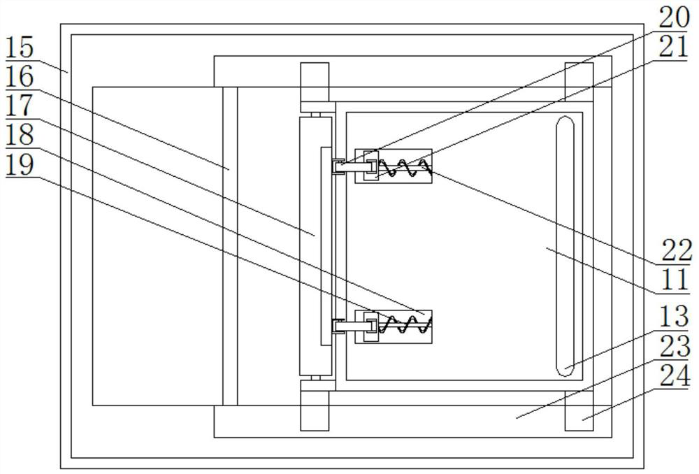
[0022] refer to figure 1 , 2 , 4, a new energy vehicle transmission device, including a box body 15, an installation cavity is provided in the box body 15, which is convenient for installation, and a power shaft 9 is run through the side wall of one end in the installation cavity to output power, and the power shaft 9 A second bevel gear 10 is fixedly sleeved on the top, a gear 7 is fixed on one end of the power shaft 9, and the gear 7 is located in the installation cavity, and a speed change assembly 5 is arranged on one side of the gear 7, and the gear 7 drives the speed change assembly 5 to move, and Speed change, the upper end of one end side wall in the installation cavity is fixed with the first sliding sleeve 6, the rotating shaft 4 is sleeved on the first sliding sleeve 6 to facilitate the rotation of the rotating shaft 4, the lower end of the rotating shaft 4 is fixed with the first bevel gear 8, and The first bevel gear 8 is meshed with the second bevel gear 10, a...
Embodiment 2
[0024] refer to figure 1 , 2, 3, 4, a new energy vehicle transmission device, including a box body 15, an installation cavity is provided in the box body 15, which is convenient for installation, and a power shaft 9 runs through the side wall of one end in the installation cavity to output power, power A second bevel gear 10 is fixedly sleeved on the shaft 9, a gear 7 is fixed on one end of the power shaft 9, and the gear 7 is located in the installation cavity, and a speed change assembly 5 is arranged on one side of the gear 7, and the gear 7 drives the speed change assembly 5 to move , to change the speed, the upper end of one end side wall in the installation cavity is fixed with the first sliding sleeve 6, the rotating shaft 4 is sleeved on the first sliding sleeve 6 to facilitate the rotation of the rotating shaft 4, and the lower end of the rotating shaft 4 is fixed with the first bevel gear 8 , and the first bevel gear 8 meshes with the second bevel gear 10, the power...
Embodiment 3
[0027] refer to figure 1 , 2 , 4, 5, a new energy vehicle transmission device, including a box body 15, an installation cavity is provided in the box body 15, which is convenient for installation, and a power shaft 9 runs through the side wall of one end in the installation cavity, and the output power, power A second bevel gear 10 is fixedly sleeved on the shaft 9, a gear 7 is fixed on one end of the power shaft 9, and the gear 7 is located in the installation cavity, and a speed change assembly 5 is arranged on one side of the gear 7, and the gear 7 drives the speed change assembly 5 to move , to change the speed, the upper end of one end side wall in the installation cavity is fixed with the first sliding sleeve 6, the rotating shaft 4 is sleeved on the first sliding sleeve 6 to facilitate the rotation of the rotating shaft 4, and the lower end of the rotating shaft 4 is fixed with the first bevel gear 8 , and the first bevel gear 8 meshes with the second bevel gear 10, th...
PUM
 Abstract
Description
Claims
Application Information
 - R&D
- Intellectual Property
- Life Sciences
- Materials
- Tech Scout
- Unparalleled Data Quality
- Higher Quality Content
- 60% Fewer Hallucinations
Browse by: Latest US Patents, China's latest patents, Technical Efficacy Thesaurus, Application Domain, Technology Topic, Popular Technical Reports.
© 2025 PatSnap. All rights reserved.Legal|Privacy policy|Modern Slavery Act Transparency Statement|Sitemap|About US| Contact US: help@patsnap.com