Supercharge Your Innovation With Domain-Expert AI Agents!

Angle-adjustable steel blade foot

A technology for adjusting angles and blade feet, which is applied in water conservancy projects, artificial islands, underwater structures, etc., can solve the problems of inability to flexibly correct the posture of the box body, and cannot adjust the angle in time, and achieve low production cost, easy operation, and easy installation The effect of simple structure

Inactive Publication Date: 2018-08-10
CHINA RAILWAY FIFTH SURVEY & DESIGN INST GRP +1
View PDF5 Cites 1 Cited by
  • Summary
  • Abstract
  • Description
  • Claims
  • Application Information

AI Technical Summary

Problems solved by technology

The present invention overcomes the shortcomings of the original steel blade feet, such as the fixed angle, the inability to adjust the angle in time during the jacking construction, and the inability to flexibly correct the posture of the box body, etc.

Method used


Image

  • Angle-adjustable steel blade foot
  • Angle-adjustable steel blade foot

Examples


Embodiment Construction

[0015] The present invention will be further described in detail below in conjunction with the accompanying drawings and specific embodiments.

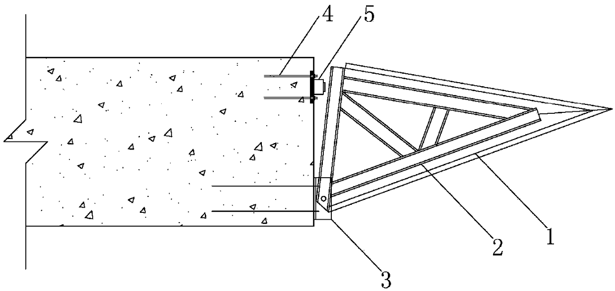
[0016] The structure of this embodiment is as figure 1 As shown, a steel blade foot device with an adjustable angle with the horizontal plane is composed of a steel blade foot 1, a steel truss 2, a fixed hinge 3, a pre-embedded flange 4, and a jack 5.

[0017] The steel blade foot 1 and the steel truss 2 are connected by welding to ensure a reliable connection between the two. The steel blade foot 1 at the bottom is used as a component for eating soil and jacking, and the steel truss 2 is used as the main force transmission component; the fixed hinge 3 is the steel truss close to The fixed nodes on the inside of the box are connected with the steel truss 2 by bolts, and the bolts can be manually adjusted;

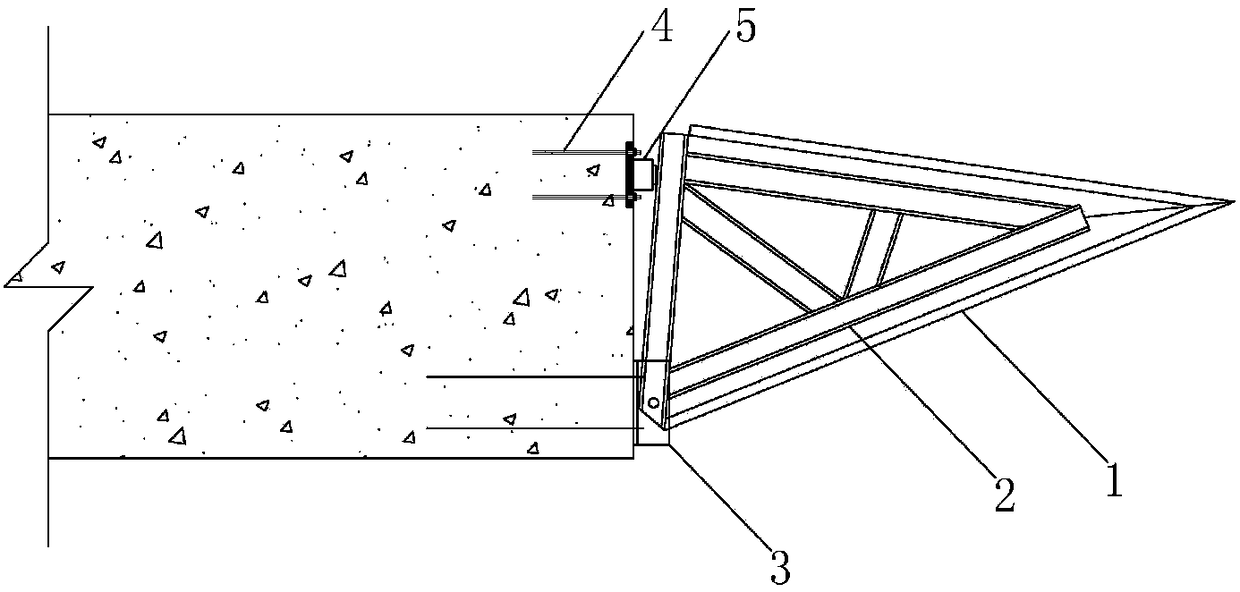
[0018] Such as figure 2 As shown, during the box culvert jacking process, the fixing hinge 3 bolts are locked; the jack 5 and ...


PUM


Abstract

The invention discloses an angle-adjustable steel blade foot, and belongs to the technical field of bridge pushing. The device is located at the front edge of a side wall of a box culvert and is usedfor eating earth and jacking during jacking construction, the blade foot as a contact device of the front end of a box body and earth has earth breaking and guide effects, and the angle-adjustable steel blade foot has the effect of adjusting the posture of the box body by adjusting the contact angle of the blade foot and earth. The device is composed of a steel blade foot, a steel truss, a jack, apre-embedded flange and a fixed hinge. The device is connected with a concrete top plate by the fixed hinge and the jack, and the angle of a welded steel frame is changed by the device under the jacking and pulling action of the jack, so that the purpose of changing the angle of the blade foot is achieved. The device has the advantages of low cost, low technical requirements and simplicity in operation and can be recycled after construction is completed, and the angle can be adjusted during the jacking construction.

Description

technical field [0001] The invention discloses an angle-adjustable steel blade foot for box culvert jacking construction, and belongs to the technical field of bridge and culvert jacking construction. Background technique [0002] The box culvert jacking process is a relatively mature construction method for road bridge and culvert construction, and it is widely used in various projects such as railways, highways, and municipal projects. During the jacking process of the box culvert, the phenomenon that the height of the box body deviates from the design height generally occurs, that is, the phenomenon of "head up" and "head tie" of the box body. [0003] As the soil-eating member at the front edge of the box culvert, the steel blade foot plays the role of soil-eating jacking and guiding. The cutting angle of the steel blade foot depends on the soil quality, and it should be about 60°. Han's attitude played a major role. At present, in the box culvert jacking construction ...

Claims


Application Information

Patent Timeline
Patent Type & Authority Applications(China)
IPC IPC(8): E02D29/045
Inventor 康路明马士让王合希孟国清江荣丰张文学尹小溪韩静刘俊
Owner CHINA RAILWAY FIFTH SURVEY & DESIGN INST GRP
Features
  • R&D
  • Intellectual Property
  • Life Sciences
  • Materials
  • Tech Scout
  • Unparalleled Data Quality
  • Higher Quality Content
  • 60% Fewer Hallucinations
Learn More