Supercharge Your Innovation With Domain-Expert AI Agents!

A Compact Heat Pipe System for Waste Heat Utilization

A technology with compact structure and heat pipe, which is applied in the field of heat pipe, can solve the problems of uncompact structure of heat pipe waste heat utilization system, affect the heat absorption area of ​​the evaporation end, and the small heat absorption range of the evaporation end, so as to improve the waste heat absorption capacity, compact structure, avoid The effect of local overheating or overcooling

Active Publication Date: 2019-03-08
赤峰金通铜业有限公司
View PDF7 Cites 0 Cited by
  • Summary
  • Abstract
  • Description
  • Claims
  • Application Information

AI Technical Summary

Problems solved by technology

[0004] In the prior art, the shape of the heat pipe affects the heat-absorbing area of ​​the evaporating end, so the heat-absorbing range of the evaporating end is generally relatively small, and sometimes it is necessary to install multiple heat pipes in the heat source to meet the heat-absorbing demand; and when there are multiple evaporating ends, Because each evaporation end is in a different position of the heat source, it will produce uneven heat absorption.
[0005] In addition, in the prior art, the waste heat utilization heat pipe device always extends the condensation end to the outside of the pipe, which occupies the external area, making the heat pipe waste heat utilization system not compact

Method used


Image

  • A Compact Heat Pipe System for Waste Heat Utilization
  • A Compact Heat Pipe System for Waste Heat Utilization
  • A Compact Heat Pipe System for Waste Heat Utilization

Examples


Embodiment Construction

[0044] The specific embodiments of the present invention will be described in detail below in conjunction with the accompanying drawings.

[0045] In this article, if there is no special explanation, when it comes to formulas, " / " means division, and "×" and "*" mean multiplication.

[0046] The specific embodiments of the present invention will be described in detail below in conjunction with the accompanying drawings.

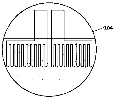
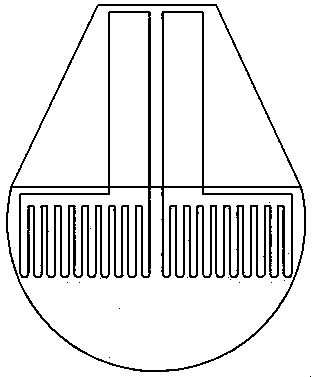
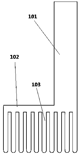
[0047] Such as Figure 1-6 As shown, a heat pipe 10 arranged in a flue and using a flue waste heat device, the heat pipe includes a vertical part 101, a horizontal part 102 and a vertical pipe 103, wherein the bottom end of the vertical part 101 communicates with the horizontal part 102, The horizontal part 102 extends from the bottom end of the vertical part 101 to a direction away from the vertical part 101, and the lower part of the horizontal part 102 communicates with a plurality of vertical pipes 103, wherein the vertical pipes 103 are the evaporation ...


PUM


Abstract

The invention provides a waste heat utilization heat pipe system compact in structure. The system comprises a heat pipe and a round pipe. The heat pipe comprises a vertical part, a horizontal part andvertical pipe bodies, wherein the bottom end of the vertical part communicates with the horizontal part, the horizontal part extends from the bottom end of the vertical part towards the position awayfrom the vertical part, the lower portion of the horizontal part communicates with the multiple vertical pipes which are evaporation ends of the heat pipe, and the vertical part is a condensation endof the heat pipe. The waste heat utilization heat pipe system compact in structure is characterized in that the round pipe is divided into an upper part and a lower part, the lower part is a flue gaschannel, the upper part is an air channel, and the vertical pipes and the horizontal part are arranged in the flue gas channel; and the vertical part is arranged in the air channel. By arranging thewhole heat pipe in the round pipe and dividing the round pipe into the upper part and the lower part, the outside space does not occupy any extra area, so that the outside space is fully utilized andthe purposes of compact structure and spacing saving are achieved.

Description

technical field [0001] The invention relates to a heat pipe technology, in particular to a heat pipe with a new structure. Background technique [0002] Heat pipe technology is a heat transfer element called "heat pipe" invented by George Grover of Los Alamos National Laboratory in the United States in 1963. It makes full use of the principle of heat conduction and phase change medium. The rapid heat transfer properties of the heat pipe quickly transfer the heat of the heating object to the heat source, and its thermal conductivity exceeds that of any known metal. [0003] Heat pipe technology was widely used in aerospace, military and other industries before. Since it was introduced into the radiator manufacturing industry, people have changed the traditional radiator design ideas and got rid of the single heat dissipation mode that only relies on high air volume motors to obtain better heat dissipation. The use of heat pipe technology enables the radiator to obtain a sati...

Claims


Application Information

Patent Timeline
Patent Type & Authority Patents(China)
IPC IPC(8): F28D15/02
CPCF28D15/0266
Inventor 邹振宁冷学礼崔琳
Owner 赤峰金通铜业有限公司
Features
  • R&D
  • Intellectual Property
  • Life Sciences
  • Materials
  • Tech Scout
  • Unparalleled Data Quality
  • Higher Quality Content
  • 60% Fewer Hallucinations
Learn More