Light-guide capillary photometer

A technology of capillary and photometer, which is applied in the field of photometer, can solve the problems of large reflection loss of metal surface, large reflection loss of light beam, and difficult injection of liquid to be tested, etc., and achieves the reduction of reflection loss, enhanced constraint ability, and convenient optical path size Effect

Inactive Publication Date: 2018-09-04
黄辉 +2
View PDF5 Cites 2 Cited by
  • Summary
  • Abstract
  • Description
  • Claims
  • Application Information

AI Technical Summary

Problems solved by technology

[0003] The traditional light guide capillary has the following disadvantages: 1. For the Teflon capillary, the principle of light guide is to use the small refractive index difference (1.3 and 1.33) between the Teflon material and the aqueous solution to constrain the beam, but when the capillary bends The light beam is easy to leak out of the capillary; 2. For the metal capillary, the reflection loss of the inner wall of the light beam is relatively large, which will lead to a large transmission loss, and the relationship between the smooth undulation of th

Method used


Image

  • Light-guide capillary photometer
  • Light-guide capillary photometer

Examples


Example Embodiment

[0038] Example 1

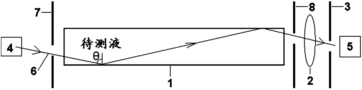
[0039] The second light reflecting device 8 is provided with an outlet for detecting light 6, and the detecting light 6 transmitted from the light guiding capillary 1 is incident on the light detector 5 through the outlet. The apertures of the probe light entrance on the first reflector 7 and the probe light exit on the second reflector 8 are adjustable. By adjusting the aperture size, the number of times the probe light 6 emitted by the light source 4 is reflected on the two reflectors can be adjusted. The aperture of the entrance on the first reflector 7 is 0.001-10mm, preferably, the aperture of the through hole is 0.005-1mm, and the aperture of the exit on the second reflector 8 is 0.001-10mm, preferably, the aperture of the through hole is 0.05 ~1mm.

[0040] Such as figure 1 As shown, a stainless steel capillary with a polished inner wall with an inner diameter of 1.0 mm is used as a light guide capillary 1.

[0041] When the detection light 6 emitted by th...

Example Embodiment

[0045] Example 2

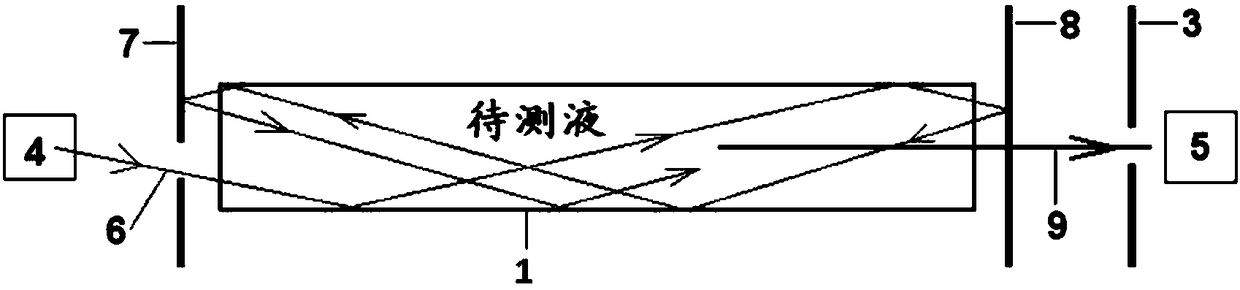
[0046] The second light reflecting device 8 is a plane structure with a complete surface, and the test sample generates fluorescence 9 under the excitation of the detection light, and the fluorescence 9 is incident on the photodetector 5 through the second light reflecting device 8.

[0047] Such as figure 2 As shown, the inner diameter of the silver capillary polished on the inner wall is 0.4 mm, which serves as the light guide capillary 1.

[0048] When the light beam 6 emitted by the light source 4 passes through a small hole with an aperture of 0.3 mm on the aluminum first reflecting device 7, it enters the light guide capillary 1. Due to the high reflectivity of the inner wall of the silver-guided light-guiding capillary 1, the detection light can be restricted.

[0049] Since two reflective devices are placed at both ends of the capillary, including the first aluminum reflective device 7 with holes and the second reflective device 8 of non-porous dielectric f...


PUM

PropertyMeasurementUnit
The inside diameter ofaaaaaaaaaa
Apertureaaaaaaaaaa
Apertureaaaaaaaaaa

Abstract

The invention relates to a light-guide capillary photometer which comprises a light source, an optical detector and a light-guide capillary used for loading a test sample, wherein reflective devices are respectively arranged at two ends of the light-guide capillary; detected light emitted by a light source is reflected by the two reflective devices to be constrained in the light-guide capillary soas to be transmitted by several times; the optical detector receives detected light or fluorescence emitted by the light-guide capillary. According to the light-guide capillary photometer disclosed by the invention, one part of the detected light is reflected and transmitted back and forth between the two reflective devices, so that the optical distance is increased, and the detection sensitivityis increased. Moreover, the constraint ability is greatly enhanced, reflection loss can be greatly reduced, the structure is simple, sample circulation is fast, and the optical distance is conveniently adjusted.

Description

technical field [0001] The invention relates to a photometer, in particular to a light guide capillary photometer. Background technique [0002] Photometric analyzers are widely used to detect the composition of liquid or gas samples (ie, the content of trace substances) (Sensors and Actuators B, vol.191, 2014, 561-566; Annu.Rev.Anal.Chem., vol.5, 2012, 1-14), its working principle is: the sample to be tested is placed in a transparent cuvette (or capillary), and the probe beam passes through the sample to be tested, thereby detecting the absorption spectrum of the sample to be tested on the probe beam (ie, a spectrophotometer) , or detect the fluorescence spectrum radiated by the sample to be measured (ie, a fluorescence photometer or a fluorimeter). [0003] The traditional light guide capillary has the following disadvantages: 1. For the Teflon capillary, the principle of light guide is to use the small refractive index difference (1.3 and 1.33) between the Teflon materi...

Claims


Application Information

Patent Timeline
IPC IPC(8): G01N21/01G01N21/64
CPCG01N21/01G01N21/6402
Inventor 黄辉渠波李雪晶
Owner 黄辉
Why Eureka
Try Eureka