power converter
A technology of power converter and voltage conversion, applied in the direction of electronic commutator, electronic commutation motor control, electrical components, etc., can solve the problems of high price and no sensor of position sensor, and achieve the effect of reducing detection error and no impact start
- Summary
- Abstract
- Description
- Claims
- Application Information
AI Technical Summary
Problems solved by technology
Method used
Image

Examples
Embodiment 1
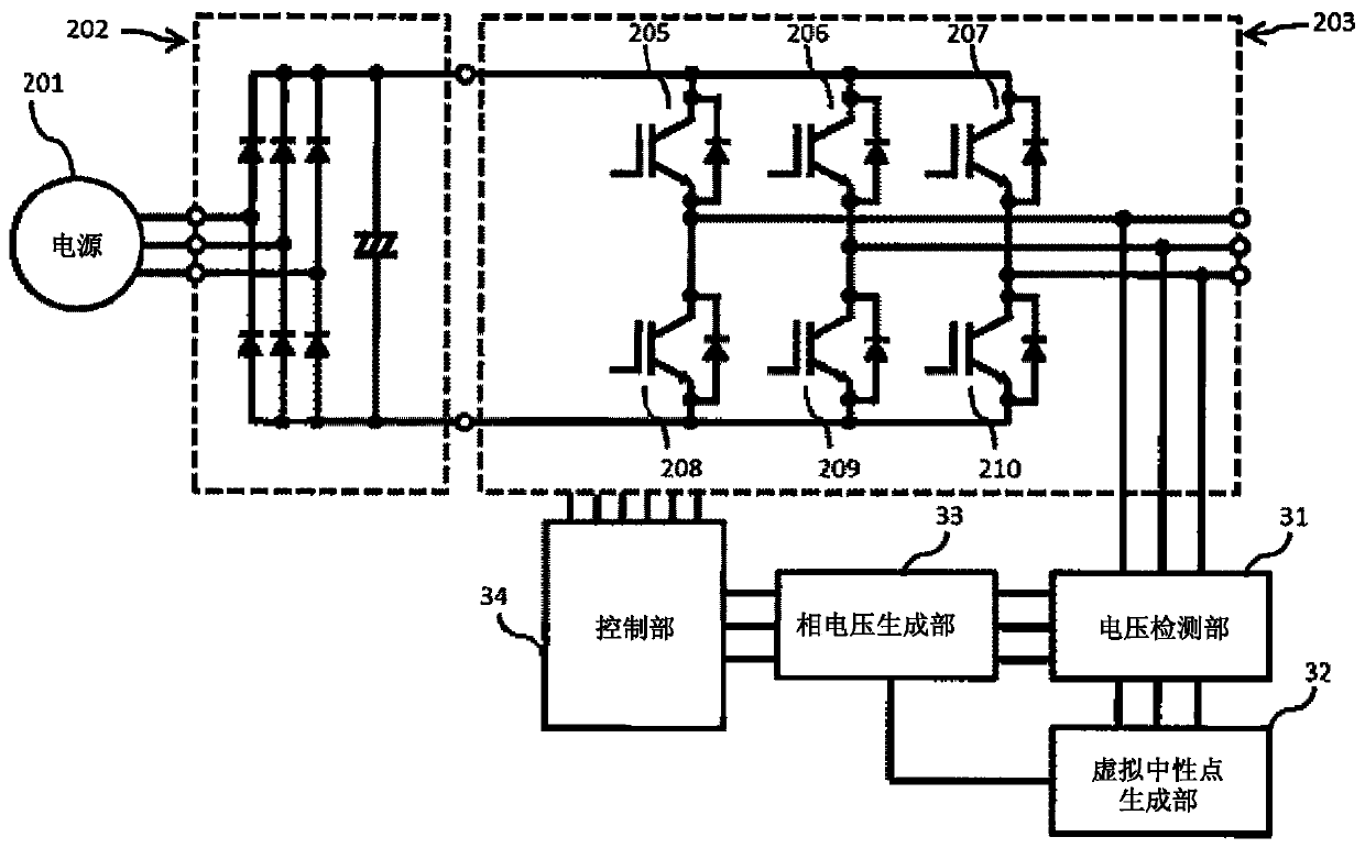
[0037] Embodiment 1 adopts a circuit structure that generates a virtual neutral point. All the three-phase lower arms are turned on, and the negative potential is output to all output phases of the power converter, and a three-phase balance state is established. Thus, a method of detecting an offset voltage based on the fact that the reference voltage input to the control unit is equal to the virtual neutral point will be described.
[0038] image 3 shows a configuration example of a power converter when phase voltage detection is performed, Figure 4~6 A schematic diagram showing one phase of the phase voltage detected by the control unit 34, Figure 7 It is a figure which shows the example of the flowchart of the process of a control part.
[0039] The induced voltage of the motor is in a balanced state. Therefore, for example, when the induced voltages of each phase of a three-phase motor are Vu, Vv, and Vw, and the virtual neutral point is Vneutral, their relationship ...
Embodiment 2
[0069] Embodiment 2 adopts a circuit structure for generating a virtual neutral point. Connect the motor to the output terminal, and input the voltage in the three-phase balanced state to the power converter. Thus, a method of detecting an offset voltage based on the fact that the reference voltage input to the control unit is equal to the virtual neutral point will be described. In addition to the motor, a voltage generating source capable of inputting a voltage in a three-phase balanced state, such as a generator and a power supply, may be connected.
[0070] Figure 8 An example of the structure of the power converter when the voltage is input from the output terminal is shown, Figure 9 It is a figure which shows the flowchart of the process of a control part.
[0071] use Figure 9 , the flow of the process of detecting the offset voltage by the control unit 84 will be described. When the detection is started (S91), with all the phases 205-210 as switching elements o...
Embodiment 3
[0091] Embodiment 3 adopts a circuit structure for generating a virtual neutral point. The method of detecting the offset voltage using the detection value of the DC voltage when the reference voltage input to the control unit is not equal to the virtual neutral point by turning on all three-phase upper arms will be described.
[0092] As one of the methods, in Figure 10 A circuit configuration in which the DC voltage detection unit 105 is added to the circuit configuration described in the first embodiment is shown in . The DC voltage detection unit 105 detects the voltage of the positive electrode potential based on the negative electrode potential of the DC conversion unit 202 .
[0093] use Figure 13 , the flow of the process of detecting the offset voltage by the control unit 104 will be described. When the detection is started (S131), the three-phase upper arms 205 to 207 which are switching elements of the AC conversion unit 203 are turned on (S132). At this time,...
PUM
 Abstract
Description
Claims
Application Information
 - R&D
- Intellectual Property
- Life Sciences
- Materials
- Tech Scout
- Unparalleled Data Quality
- Higher Quality Content
- 60% Fewer Hallucinations
Browse by: Latest US Patents, China's latest patents, Technical Efficacy Thesaurus, Application Domain, Technology Topic, Popular Technical Reports.
© 2025 PatSnap. All rights reserved.Legal|Privacy policy|Modern Slavery Act Transparency Statement|Sitemap|About US| Contact US: help@patsnap.com