Balancing valve and hydraulic lifting system as well as operation machine

A hydraulic system and balance valve technology, which is applied in mechanical equipment, hoisting devices, fluid pressure actuators, etc., can solve problems such as hydraulic system shock and vibration, and achieve the effect of small hydraulic shock and stable system

Active Publication Date: 2018-09-21
GUANGXI LIUGONG MASCH CO LTD
View PDF5 Cites 1 Cited by
  • Summary
  • Abstract
  • Description
  • Claims
  • Application Information

AI Technical Summary

Problems solved by technology

[0005] The technical problem to be solved by the present invention is to provide a balance valve, hydraulic lifting system and working machinery to avoid the impact of the system when the lif

Method used


Image

  • Balancing valve and hydraulic lifting system as well as operation machine

Examples


Example Embodiment

[0023] Specific embodiments are described below with reference to the accompanying drawings.

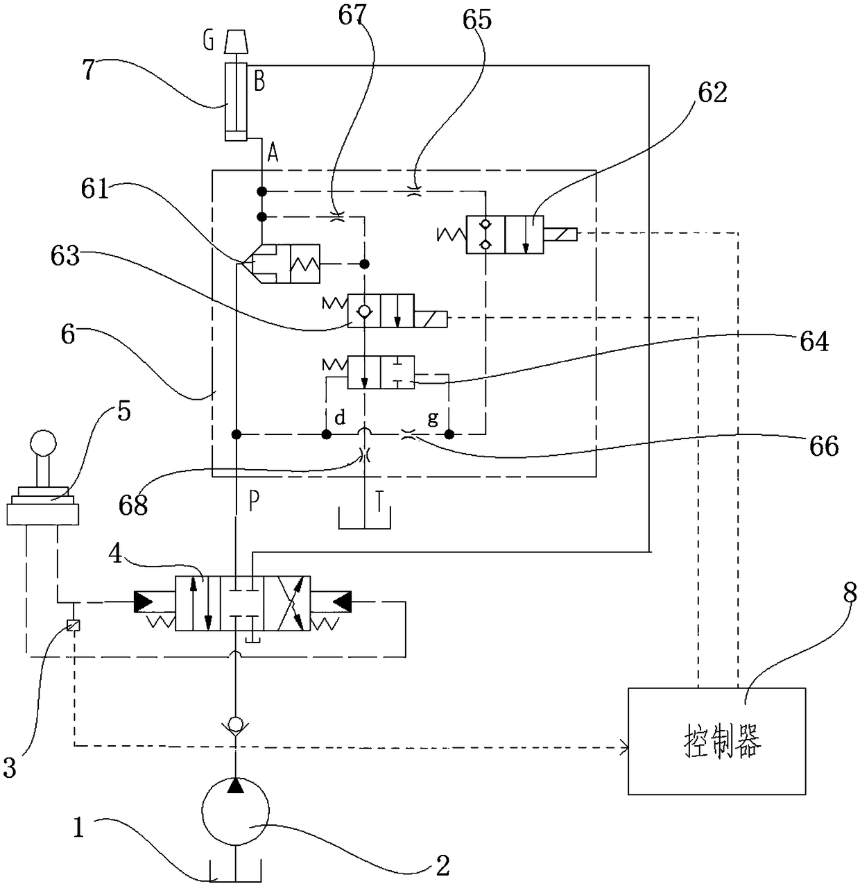
[0024] The lift hydraulic system in this embodiment may be a loader arm lift hydraulic system, an excavator arm lift hydraulic system, a mining dump truck body lift hydraulic system, a crane boom lift hydraulic system, or a forklift truck lift hydraulic system. Fork lift hydraulic system, if the connecting oil circuit of the rod cavity and the rodless cavity of the hydraulic cylinder is exchanged, it can also be the front and rear swing hydraulic system of the excavator stick and so on. The lifting hydraulic system can be used for the hydraulic system for lifting the heavy object G by the expansion and contraction of the hydraulic cylinder.

[0025] like figure 1 As shown, the lift hydraulic system in this embodiment includes a lift cylinder 7, a lift cylinder control valve 4, a lift control device for controlling the lift cylinder control valve, and a lift operation detection devic...


PUM


Abstract

The invention relates to a balancing valve. In order to solve the problem of impact shaking of the hydraulic system caused when the existing lifting hydraulic system falls back, the invention providesa balancing valve. The balancing valve is characterized by comprising a forward oil inlet, a forward oil outlet and an oil returning opening and further comprising a hydraulic control valve, a pressure difference control oil way and a reverse conduction control oil way of a hydraulic control valve, wherein the pressure difference control oil way comprises a first electromagnetic switching valve and a second throttling valve which are successively connected in series from the forward oil outlet to the forward oil inlet; the reverse conduction control oil way of the hydraulic control valve comprises a third throttling valve with the oil inlet end connected with the forward oil outlet; a second electromagnetic switching valve and a pressure difference control switching valve which are connected in series are arranged on an oil way between the oil outlet end of the third throttling valve and the oil returning opening; a hydraulic control end of the hydraulic control valve is connected with the oil outlet end of the third throttling valve; hydraulic control ends of two ends of the pressure difference control switching valve are respectively connected with the oil inlet end and the oiloutlet end of the second throttling valve. According to the balancing valve, no impact is generated when the hydraulic control valve is reversely switched on; the stability of the hydraulic control valve during reverse conduction is improved.

Description

technical field [0001] The present invention relates to a hydraulic component, more particularly, to a balance valve, a hydraulic lifting system and an operating machine. Background technique [0002] Balance valves are used in various engineering machinery, especially in mechanical equipment with lifting function. The function of the balance valve is to prevent the working parts from falling at an overspeed due to its own weight, or to prevent the unstable movement of the speed out of control due to the self-weight during the descending movement, and to avoid the occurrence of accidental danger. [0003] The existing balance valve has a forward oil inlet, a forward oil outlet, and a hydraulic control oil port; a check valve and a switch valve are connected in parallel between the forward oil inlet and the forward oil outlet, and the hydraulic control of the switch valve The end is connected with the hydraulic control oil port, and the check valve is unidirectionally connec...

Claims


Application Information

Patent Timeline
IPC IPC(8): F15B13/02B66F9/22
CPCB66F9/22F15B13/023
Inventor 边心文梁振国姜炜王允刘光喜
Owner GUANGXI LIUGONG MASCH CO LTD
Why Eureka
Try Eureka