Check patentability & draft patents in minutes with Patsnap Eureka AI!

Reactive power compensation method

A technology of power compensation and compensation amount, applied in reactive power compensation, AC network voltage adjustment, etc., can solve problems such as aging, speeding up lines, and increasing line losses, and achieve reduced construction costs, high-precision phase-separated compensation, and convenient and quick installation Effect

Inactive Publication Date: 2018-09-28
NORTHEAST AGRICULTURAL UNIVERSITY
View PDF3 Cites 0 Cited by
  • Summary
  • Abstract
  • Description
  • Claims
  • Application Information

AI Technical Summary

Problems solved by technology

[0004] Although reactive power is not billed, the higher the reactive power, the lower the power factor will be. The smaller the power factor is, the smaller the active power will be, and the absolute value of the current in the line will increase, which will increase the line loss and speed up the line. Aging and other issues

Method used


Image

  • Reactive power compensation method

Examples


Embodiment 1

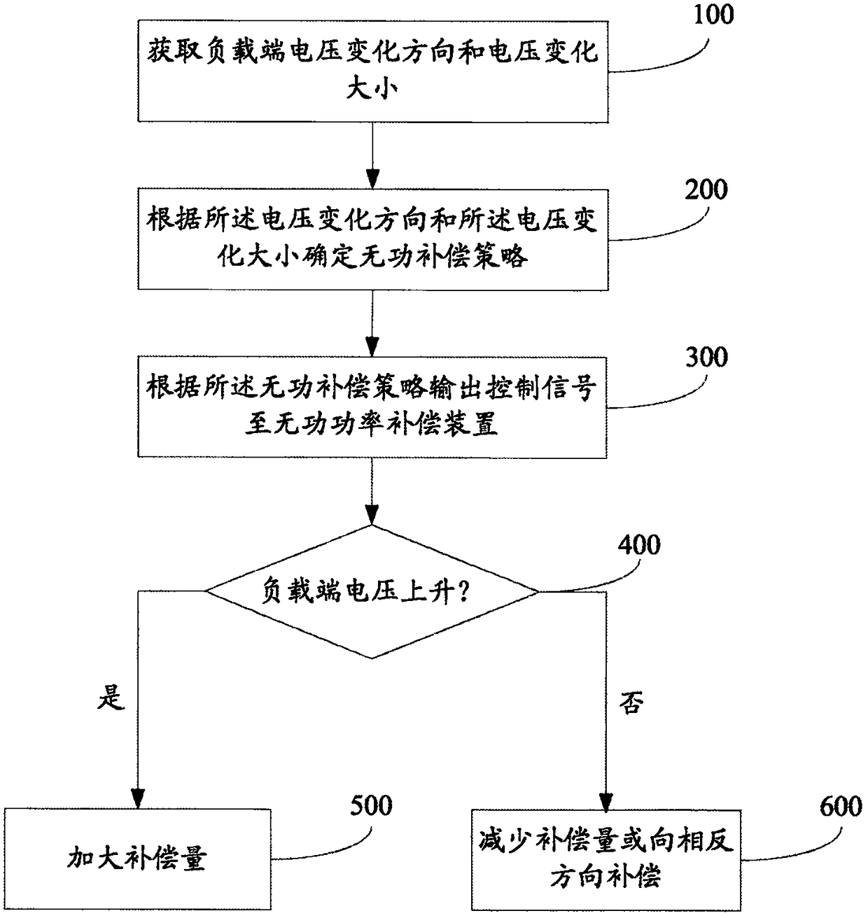
[0030] figure 1 It is a flow chart of Embodiment 1 of the real reactive power compensation method of the present invention. Such as figure 1 Said, said method comprises:

[0031] Step 100: Obtain the change direction and magnitude of the voltage change at the load terminal.

[0032] Step 200: Determine a reactive power compensation strategy according to the voltage change direction and the voltage change magnitude, the reactive power compensation strategy includes a compensation direction and a compensation amount, wherein the compensation direction is determined according to the voltage change direction, and according to The magnitude of the voltage change determines the magnitude of the compensation amount.

[0033] Step 300: Output a control signal to a reactive power compensation device according to the reactive power compensation strategy, and the reactive power compensation device is set at the load end.

[0034] Step 400: Judging whether the load terminal voltage ha...

Embodiment 2

[0041] The difference from Embodiment 1 is that in this embodiment, the three-phase power at the load end is respectively provided with reactive power compensation devices, and the voltages of the three-phase power are respectively compensated by different reactive power compensation devices. By obtaining the voltage change direction and voltage change magnitude of the three-phase power at the load end, the three-phase power is compensated respectively. The compensation process is the same as that in Embodiment 1.

[0042] Wherein, the reactive power compensation device includes a plurality of compensation branches, and the reactive power compensation strategy is any combination of the plurality of compensation branches. The compensation amounts of the multiple compensation branches are the same or different. The compensation branch is a capacitor.

[0043] For example, the reactive power compensation device of each phase is equipped with 3 compensation branches respectively....


PUM


Abstract

The invention discloses a reactive power compensation method, and belongs to the technical field of the reactive compensation. The method comprises the following steps: acquiring a load-end voltage change direction and voltage change; determining a reactive compensation policy according to the voltage change direction and the voltage change, wherein the reactive compensation policy comprises a compensation direction and compensation dosage, determining a compensation direction according to the voltage change direction, and determining the compensation dosage according to the voltage change; outputting a control signal to a reactive power compensation device according to the reactive compensation policy, wherein the reactive power compensation device is arranged at the load end; judging whether the load-end voltage is raised, and increasing the compensation dosage if the load-end voltage is raised; and reducing the compensation dosage or compensating to the reverse direction if the load-end voltage is not raised. The compensation policy is decided by detecting the load-end voltage change, the use of the current transformer is cancelled, and a series of problems is caused by adding the current transformer is avoided, the mounting is convenient and fast, the construction cost is reduced, and the configuration is more convenient and flexible.

Description

technical field [0001] The invention relates to the field of reactive power compensation, in particular to a reactive power compensation method. Background technique [0002] In the distribution network, the reactive power generated by the power generator and the power of the transmission line are often insufficient to meet the reactive power demand of a large number of motors, transformers, reactors, fluorescent lamps and other inductive loads in the network and the reactive power loss in the system. , which often leads to a decrease in the power factor of the grid and a decrease in the utilization rate of the grid system. In order to reduce active power loss and voltage drop, reduce loss in power transmission, ensure safe, economical and efficient operation of the power grid, and improve the capacity and quality of power transmission, it is usually necessary to perform nearby reactive power compensation or regulation. At present, reactive power compensation by switching p...

Claims


Application Information

Patent Timeline
Patent Type & Authority Applications(China)
IPC IPC(8): H02J3/16
CPCH02J3/16Y02E40/30
Inventor 房俊龙甄景龙高三策聂语李素旋
Owner NORTHEAST AGRICULTURAL UNIVERSITY
Features
  • R&D
  • Intellectual Property
  • Life Sciences
  • Materials
  • Tech Scout
  • Unparalleled Data Quality
  • Higher Quality Content
  • 60% Fewer Hallucinations
Learn More