Supercharge Your Innovation With Domain-Expert AI Agents!

Fluid product dispenser

A fluid dispenser, the technology of the dispenser, applied in the direction of the spray device, the single hand-held device, etc., can solve the problem of not easy to assemble or install the dispenser, and achieve the effect of preventing any mixing

Active Publication Date: 2020-12-22
APTAR FRANCE SAS
View PDF6 Cites 0 Cited by
  • Summary
  • Abstract
  • Description
  • Claims
  • Application Information

AI Technical Summary

Problems solved by technology

Additionally, the features of incorporating the dispenser head inside the deformable housing and fastening the flexible pouch directly to the dispenser head make it difficult to assemble or install the dispenser

Method used


Image

  • Fluid product dispenser
  • Fluid product dispenser
  • Fluid product dispenser

Examples


Embodiment Construction

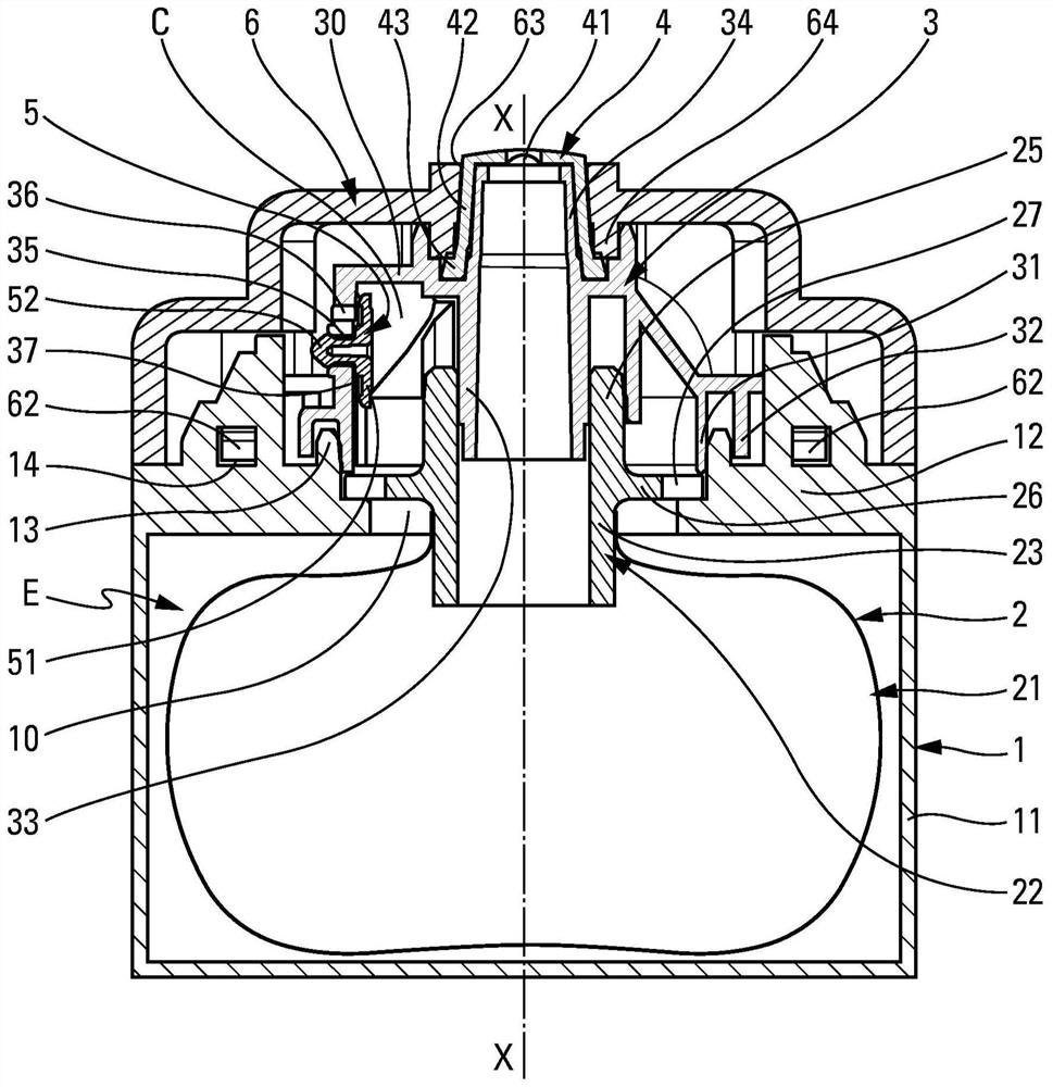
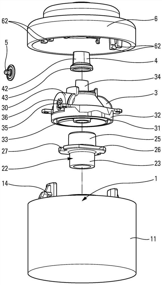
[0019] refer to figure 1 and figure 2 Both, while describing in detail the structure and operation of a fluid dispenser made in accordance with the present invention. The dispenser comprises a number of component elements, namely: a deformable outer shell 1 ; a flexible inner bag 2 ; a head piece 3 ; a fluid dispenser valve 4 ; an inlet valve 5 ; Most component elements can be produced by injection molding of suitable plastic materials. These components are assembled together along the longitudinal axis.

[0020] The deformable housing 1 is preferably made in one piece and may assume any shape suitable for manual deformation or extrusion. In more detail, the housing 1 comprises a cover 11 to which is connected at its top part an annular flange 12 defining an access channel 10 allowing access to the interior of the cover 11 . The annular flange 12 forms an annular rib 13 which protrudes upwards in the vicinity of the inlet channel 10 . The annular flange 12 also forms two...


PUM


Abstract

A fluid dispenser comprising a deformable outer shell (1) and a flexible inner pouch (2) arranged inside the housing (1) so as to confine an air-filled compressed The space (E), the bag (2) contains the fluid for dispensing through the dispenser valve (4), the compression space (E) communicates with the outside through the inlet valve (5), so that the deformation of the housing (1) makes the compression space The air contained in (E) is under pressure, the air under pressure acts on the bag (2), so that the fluid therein is then forced through the dispenser valve (4), which also consists of a valve mounted on the housing (1) And the head piece (3) on the bag (2), the head piece (3) includes a first valve support (34) and a second valve support (35), and the distributor valve (4) is installed on the first valve On the support part (34), and the intake valve (5) is installed on the second valve support part (35); the distributor is characterized in that it also includes a cover (6), the cover (6) is sealed fastened on the deformable shell (1), the cover (6) keeps the head part (3) in place on the deformable shell (1) and the flexible inner bag (21), the cover ( 6) Including a window (63) in which the dispenser valve (4) is positioned.

Description

technical field [0001] The present invention relates to a fluid dispenser comprising a deformable outer shell and a flexible inner bag arranged inside the deformable outer shell so as to define a A compressed space filled with air, the flexible inner pouch contains fluid for dispensing through the fluid dispenser valve, the compressed space communicates with the outside through the inlet valve, so that deformation of the deformable shell closes the inlet valve and makes the compressed space The air contained within is under pressure, and the air under pressure acts on the flexible inner bag, causing the fluid therein to then be forced through the fluid dispenser valve. Dispensers of this type find advantageous application in the fields of cosmetics, pharmacy and perfumery. Background technique [0002] In the prior art, for example known document FR2821766, describes a dispenser of this type comprising a squeezable outer shell provided with an inlet valve and a flexible inn...

Claims


Application Information

Patent Timeline
Patent Type & Authority Patents(China)
IPC IPC(8): B05B11/00B05B11/04
CPCB05B11/047B05B11/0044B05B11/007B05B11/0072B05B11/048
Inventor 法比安·亚当
Owner APTAR FRANCE SAS
Features
  • R&D
  • Intellectual Property
  • Life Sciences
  • Materials
  • Tech Scout
  • Unparalleled Data Quality
  • Higher Quality Content
  • 60% Fewer Hallucinations
Learn More