Check patentability & draft patents in minutes with Patsnap Eureka AI!

Solar drying box, drying rack and drying components

A technology of drying boxes and drying racks, which is applied in the direction of solar thermal energy, solar thermal power generation, solar collectors, etc., can solve the problems of inconvenience, energy waste, consumption, etc., achieve simple drying operation, reduce energy consumption, and operate convenient effect

Active Publication Date: 2020-09-25
苏州汇思阳光科技有限公司
View PDF6 Cites 0 Cited by
  • Summary
  • Abstract
  • Description
  • Claims
  • Application Information

AI Technical Summary

Problems solved by technology

[0002] At present, the drying or drying of crops usually spreads the materials to be dried on the drying site for drying or drying by drying equipment. Since the drying site is fixed, it is very inconvenient to transport the materials to the drying site for each drying. ; while the use of drying equipment will need to consume energy such as coal, electric energy, resulting in waste of energy

Method used


Image

  • Solar drying box, drying rack and drying components
  • Solar drying box, drying rack and drying components
  • Solar drying box, drying rack and drying components

Examples


Embodiment 1

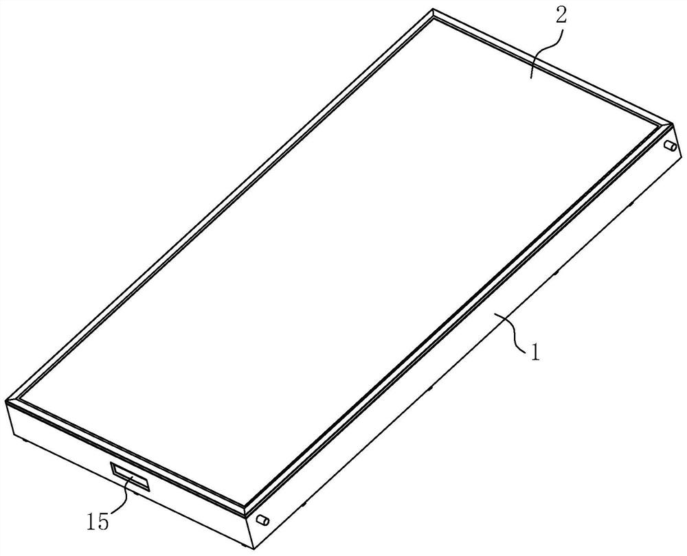
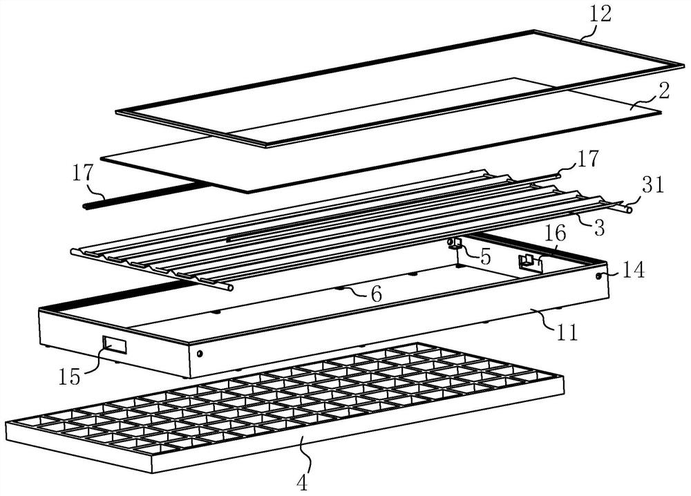
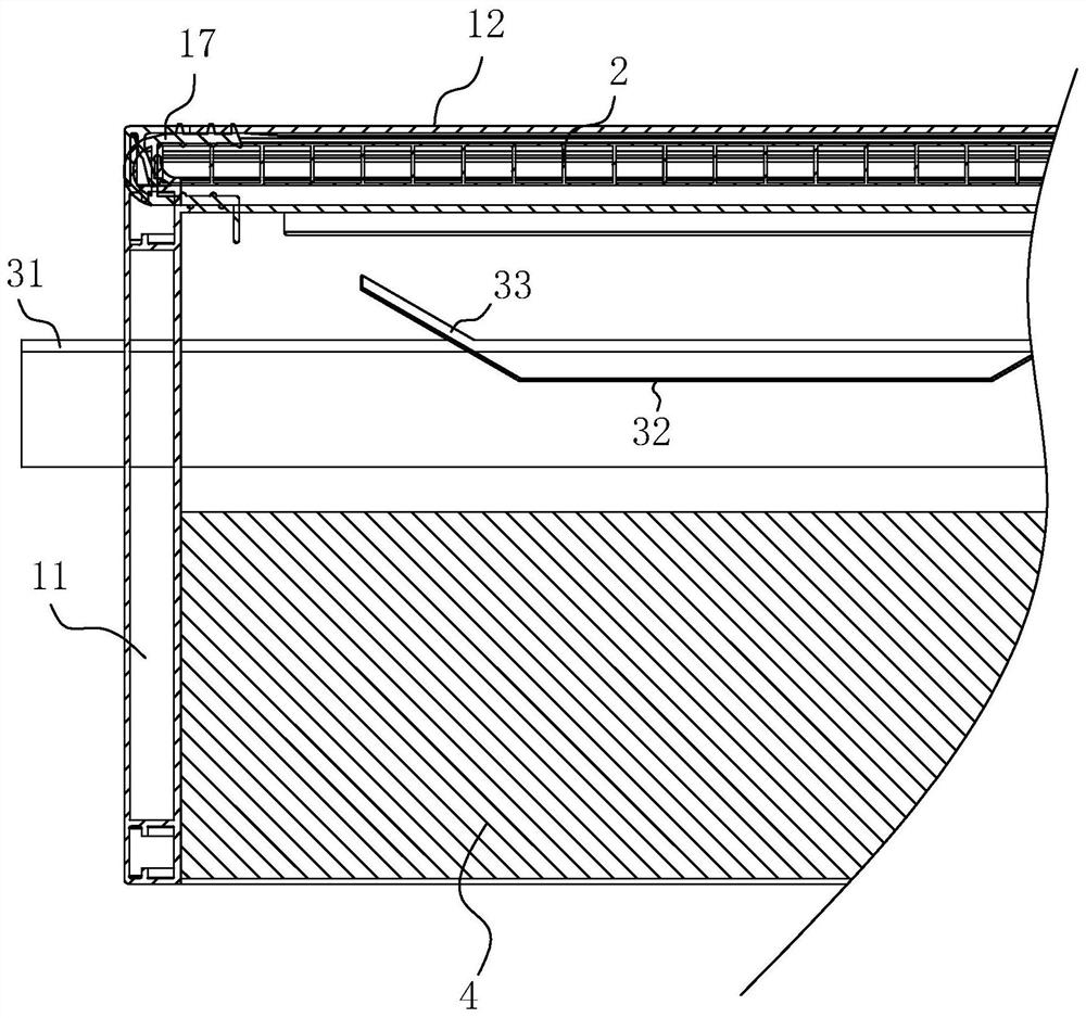
[0056] A kind of solar drying oven, such as figure 1 and figure 2 As shown, it includes: an installation frame body 1, the installation frame body 1 includes an outer frame 11, and a bead 12 engaged with the outer frame 11, and an installation groove 13 is formed between the bead bar 12 and the outer frame 11 (see Figure 4 ); inserted into the installation groove 13 and pressed against the light-transmitting heat insulation board 2 assembled with the installation frame 1 by the pressure strip 12; the solar heat collector core 3 carried on the installation frame 1, the solar heat collector core 3 is provided with a supporting rod 31, and the outer frame 11 is provided with a mounting hole 14 compatible with the supporting rod 31, and the supporting rod 31 is plugged into the mounting hole 14; and, it is detachably assembled on the mounting frame 1 The material storage box 4 used to hold the materials to be dried, the solar heat collector core 3 is located between the light-t...

Embodiment 2

[0067] A drying component such as Figure 5 and Image 6 As shown, it includes: a drying rack and a drying box as described in Embodiment 1, and the drying rack is used to place the drying box.

[0068] Wherein, the drying frame includes: a supporting frame 7, in which an accommodating opening 71 compatible with the outer frame 11 is formed; a plurality of supporting corners for supporting the drying box carried around the supporting frame 7 8. A plurality of support angle codes 8 encircle and form an accommodating space for the drying box to be placed and matched with the outer frame 11; When placed in the opening 71 , the support rod set 9 can be folded to fit the drying box and limit the drying box in the accommodating opening 71 .

[0069] Specifically, the support frame 7 is generally a rectangular frame, assembled from square steel or other standard profiles by welding or bolting.

[0070] The support angle bracket 8 includes: a first support part 81 fixed to the oute...

Embodiment 3

[0076]A drying component, the difference between this embodiment and Embodiment 2 is that, as Figure 7 and Figure 8 As shown, a first reinforcing rod 101 and a second reinforcing rod 102 are respectively hinged on both sides of the supporting frame 7, and the free ends of the first reinforcing rod 101 and the second reinforcing rod 102 are detachably connected to the second supporting rod 92 by bolts. , and when the drying box is placed in the accommodating port 71, and the first support rod 91 and the second support rod 92 are rotated to fit the drying box, the first reinforcing rod 101 and the second reinforcing rod 102 can be rotated To fit the first support rod 91 and the second support rod 92; the first reinforcing rod 101 is provided with a third connecting hole 103, and the second reinforcing rod 102 is provided with a fourth connecting hole 104, and when the first When the reinforcing rod 101 and the second reinforcing rod 102 are rotated to fit the first supporting...


PUM


Abstract

The invention relates to a solar drying box, a drying frame and a drying assembly. The solar drying box comprises a mounting frame, a light transmitting heat insulation plate, a solar heat collectionpanel core and a material storing box, wherein the mounting frame comprises an outer frame body and a pressing strip which is connected to the outer frame body in a clamped mode, and a mounting grooveis formed between the pressing strip and the outer frame body; the light transmitting heat insulation plate is inserted and connected into the mounting groove and is pressed by the pressing strip inan abutting mode to be assembled onto the mounting frame; the solar heat collection panel core is carried on the mounting frame; and the material storing box is detachably assembled onto the mountingframe and used for containing to-be-dried materials, the solar heat collection panel core is located between the light transmitting heat insulation plate and the material storing box, the heat collection surface of the solar heat collection panel core faces the light transmitting heat insulation plate, and the heat radiating surface of the solar heat collection panel core faces the material storing box. Material drying is performed by combining the solar heat collection panel core and the material storing box, thus energy consumption is reduced, modularization of drying equipment is achieved,limit of the field to air-drying operation is reduced, and operation is more convenient.

Description

technical field [0001] The invention relates to the technical field of drying devices, and more particularly, to a solar drying box, a drying rack and a drying assembly. Background technique [0002] At present, the drying or drying of crops is usually done by spreading the materials to be dried on the drying site for drying or drying by drying equipment. Since the drying site is fixed, the materials need to be transported to the drying site for each drying, which is very inconvenient. ; And the use of drying equipment needs to consume coal, electricity and other energy, resulting in energy waste. SUMMARY OF THE INVENTION [0003] In view of the deficiencies in the prior art, the first purpose of the embodiments of the present invention is to provide a solar drying box, which has the advantages of convenient drying and reduced energy consumption. [0004] The above-mentioned technical purpose of the embodiment of the present invention is achieved through the following tec...

Claims


Application Information

Patent Timeline
Patent Type & Authority Patents(China)
IPC IPC(8): F26B9/06F26B25/00F24S10/50
CPCF26B9/06F26B25/00Y02E10/44
Inventor 郭玉波
Owner 苏州汇思阳光科技有限公司
Features
  • R&D
  • Intellectual Property
  • Life Sciences
  • Materials
  • Tech Scout
  • Unparalleled Data Quality
  • Higher Quality Content
  • 60% Fewer Hallucinations
Learn More