
Antistatic device for processing of electronic components

An electronic component, anti-static technology, applied in the direction of electrical components, static electricity, etc., can solve the problems of electronic component damage, poor processing, poor positioning effect, etc., to improve production yield, improve processing effect, and improve yield Effect

Inactive Publication Date: 2018-10-19
芜湖汉科信息技术有限公司
View PDF5 Cites 3 Cited by
  • Summary
  • Abstract
  • Description
  • Claims
  • Application Information

AI Technical Summary

Problems solved by technology

[0002] Electronic components are components of electronic components and electric small machines and instruments. They are often composed of several parts and can be used in similar products. They often refer to certain parts in industries such as electrical appliances, radios, and instruments, such as capacitors and transistors. The general term for sub-components such as hairsprings and clockwork, common ones are diodes, etc., and in the process of component production, static electricity will be generated, and electronic components are precision objects, and electronic components will be damaged by static electricity , at present, the existing anti-static structure on the market has a single function, and the ion fan cannot be adjusted, and it is impossible to carry out all-round anti-static work on electronic components, which reduces the production efficiency of the staff, and the electronic components are in the process of production. Due to the poor positioning effect, it will lead to poor processing and other situations. For this reason, the present invention proposes an anti-static device for electronic component processing to solve the above problems

Method used


Image

  • Antistatic device for processing of electronic components
  • Antistatic device for processing of electronic components
  • Antistatic device for processing of electronic components

Examples


Embodiment Construction

[0019] In order to make the purpose, technical solutions and advantages of the embodiments of the present invention clearer, the technical solutions in the embodiments of the present invention will be clearly and completely described below in conjunction with the drawings in the embodiments of the present invention. Obviously, the described embodiments It is a part of embodiments of the present invention, but not all embodiments. Based on the embodiments of the present invention, all other embodiments obtained by persons of ordinary skill in the art without creative efforts fall within the protection scope of the present invention.

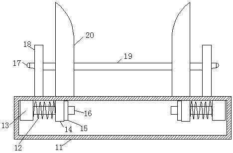
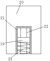
[0020] see Figure 1-5 , the present invention provides a technical solution: an anti-static device for processing electronic components, including a worktable 1, a conveyor belt 2 is provided on the worktable 1, a plurality of electronic component placement devices 3 are provided on the conveyor belt 2, and a plurality of Component placement dev...


PUM


Abstract

The invention discloses an antistatic device for processing of electronic components. The antistatic device comprises a working table, wherein a conveying belt is arranged on the working table; a plurality of electronic component placement devices are placed on the conveying belt and arranged on the conveying belt uniformly; support frames are arranged on the two sides of the working table; a guide rail is arranged between the two support frames; ion fans are arranged on the guide rail and connected with the guide rail through steering devices; each steering device comprises a connecting block, one end of the connecting block is connected with the guide rail, a fixed rack is arranged at the other end of the connecting block and fixedly connected with a limiting ring, and a spherical hingeis movably arranged in the limiting ring and connected with the corresponding ion fan; each electronic component placement device comprises a base which is arranged on the conveying belt, a group of symmetric positioning plates are arranged on the base, and a movable bottom plate is arranged between the two positioning plates. By means of cooperation of the steering devices and the ion fans, omnibearing antistatic treatment can be performed on the electronic components, and rate of finished products is increased.

Description

technical field [0001] The invention relates to the technical field of processing electronic components, in particular to an antistatic device for processing electronic components. Background technique [0002] Electronic components are components of electronic components and electric small machines and instruments. They are often composed of several parts and can be used in similar products. They often refer to certain parts in industries such as electrical appliances, radios, and instruments, such as capacitors and transistors. The general term for sub-components such as hairsprings and clockwork, common ones are diodes, etc., and in the process of component production, static electricity will be generated, and electronic components are precision objects, and electronic components will be damaged by static electricity , at present, the existing anti-static structure on the market has a single function, and the ion fan cannot be adjusted, and it is impossible to carry out a...

Claims


Application Information

Patent Timeline
IPC IPC(8): H05F3/06
CPCH05F3/06
Inventor 宣以政杨康马成根
Owner 芜湖汉科信息技术有限公司
Features
  • Generate Ideas
  • Intellectual Property
  • Life Sciences
  • Materials
  • Tech Scout
  • Unparalleled Data Quality
  • Higher Quality Content
  • 60% Fewer Hallucinations
Learn More