
Blanking, bending and punching composite die

A compound mold, blanking and bending technology, applied in the direction of perforating tools, forming tools, manufacturing tools, etc., can solve the problems of high energy consumption, waste of production time, and reduced production efficiency, so as to reduce costs, reduce the number of uses, and improve production efficiency effect

Active Publication Date: 2018-10-30
苏州吉润汽车零部件有限公司
View PDF5 Cites 0 Cited by
  • Summary
  • Abstract
  • Description
  • Claims
  • Application Information

AI Technical Summary

Problems solved by technology

This will cause the following disadvantages: (1) the number of molds and equipment required is large, the energy consumption is large, and the cost increases; (2) the transfer of parts between each equipment and the positioning operation on each pair of molds during the forming process It is cumbersome, wastes production time, and reduces production efficiency; (3) The positioning error and forming error of the parts on each pair of molds will accumulate, resulting in a large total dimensional error of the parts and affecting the dimensional accuracy of the parts

Method used


Image

  • Blanking, bending and punching composite die
  • Blanking, bending and punching composite die
  • Blanking, bending and punching composite die

Examples


Embodiment Construction

[0055] The following will clearly and completely describe the technical solutions in the embodiments of the present invention with reference to the accompanying drawings in the embodiments of the present invention. Obviously, the described embodiments are only part of the embodiments of the present invention, not all of them. Based on the embodiments of the present invention, all other embodiments obtained by persons of ordinary skill in the art without creative efforts fall within the protection scope of the present invention.

[0056] It should be noted that if there is a directional indication (such as up, down, left, right, front, back...) in the embodiment of the present invention, the directional indication is only used to explain the position in a certain posture (as shown in the accompanying drawing). If the specific posture changes, the directional indication will also change accordingly.

[0057] In addition, if there are descriptions involving "first", "second" and ...


PUM


Abstract

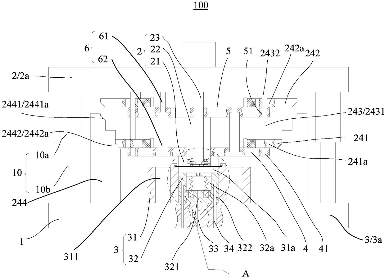
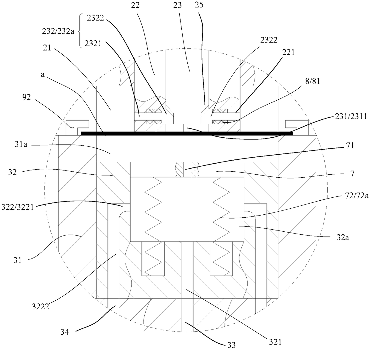
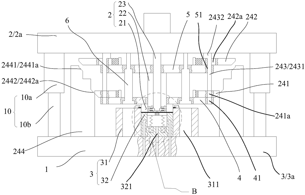
The invention discloses a blanking, bending and punching composite die which comprises a machine seat, an upper die body and a lower die body. The upper die body comprises an upper die plate, a blanking male die, a bending male die and a punching male die. The upper die plate is mounted on the machine seat in an up-down moving mode. The punching male die is fixedly mounted on the upper die plate.The blanking male die and the bending male die are mounted on the upper die plate through a switching connecting mechanism. At the blanking position, the blanking male die is fixedly connected to theupper die plate and continues to move downwards, and the blanking male die is movably connected with the upper die plate upwards; at the bending position, the bending male die is fixedly connected tothe upper die plate and continues to move downwards, the bending male die is movably connected with the upper die plate upwards; and at the punching position, the punching male die protrudes out of the blanking male die downwards and continues to moving downwards and / or protrudes out of the bending male die in the lateral direction. The lower die body comprises a lower die plate. The lower die plate is fixedly mounted on the machine seat and provided with a blanking female die and a bending female die. A punching channel is formed in the upper portion of the lower die plate. The number of useddies is decreased, and the precision of parts is improved.

Description

technical field [0001] The invention relates to the technical field of die design, in particular to a composite die for blanking, bending and punching. Background technique [0002] Blanking refers to punching out parts of the required shape from the sheet metal, punching refers to punching holes of the required shape on the workpiece, and bending refers to bending the blank into parts with a certain angle and shape. The basic process method commonly used in forming. However, in reality, the stamping and forming of many parts requires blanking, punching, and bending, often requiring multiple molds and multiple equipment to complete the forming of the parts in sequence. This will cause the following disadvantages: (1) the number of molds and equipment required is large, the energy consumption is large, and the cost increases; (2) the transfer of parts between each equipment and the positioning operation on each pair of molds during the forming process It is cumbersome, wast...

Claims


Application Information

Patent Timeline
IPC IPC(8): B21D37/10B21D28/14B21D28/34
Inventor 罗强赵娟
Owner 苏州吉润汽车零部件有限公司
Learn More