Polishing equipment
An equipment and technology for polishing rollers, applied in the polishing field, can solve the problems of reducing the polishing efficiency of steel balls, consuming too much manpower, and large dust, avoiding pollution and waste of human resources, improving polishing efficiency, and simple operation.
- Summary
- Abstract
- Description
- Claims
- Application Information
AI Technical Summary
Problems solved by technology
Method used
Image
Examples
Embodiment 1
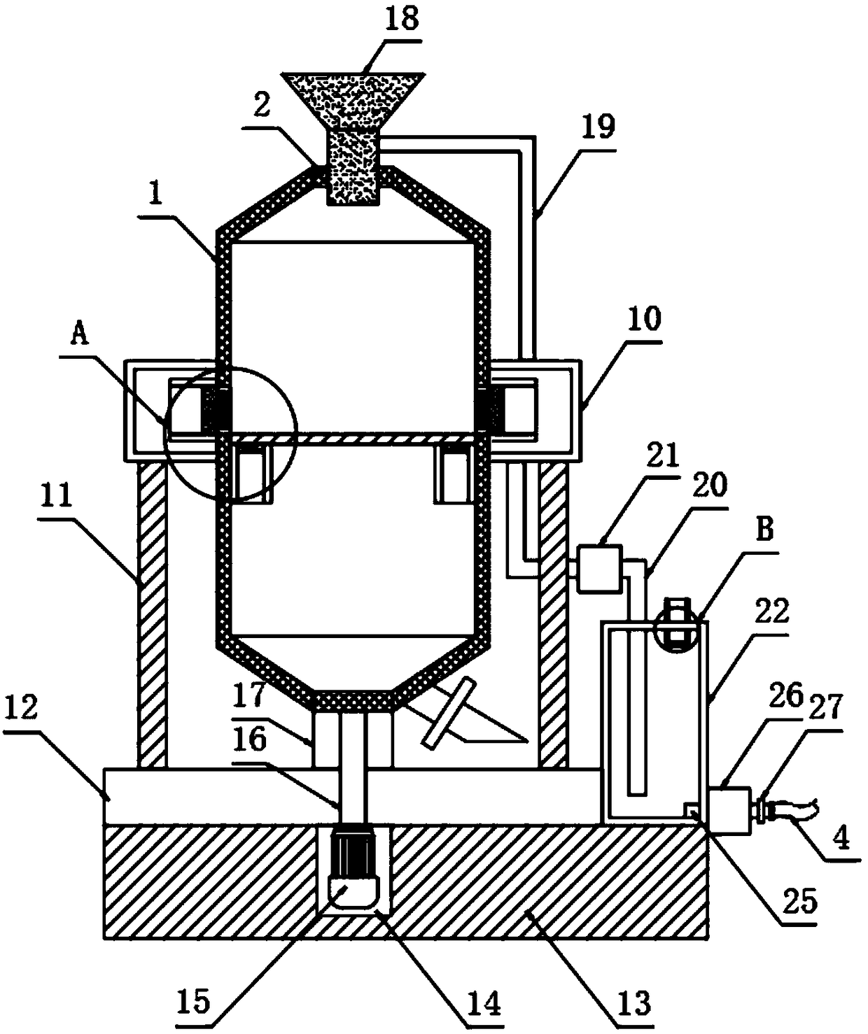
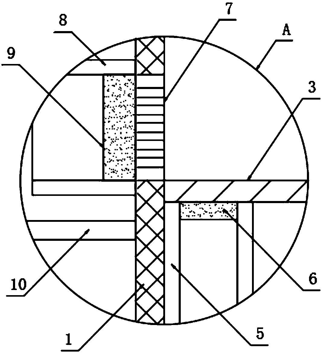
[0022] The present invention provides such Figure 1-3 A kind of polishing equipment shown, comprises polishing cylinder 1, and described polishing cylinder 1 top is provided with feeding inlet 2 and bottom is provided with support block 17, and described polishing cylinder 1 interior is provided with barrier plate 3, and described barrier plate 3 Both sides of the bottom are provided with a transition pipe 5, the interior of the transition pipe 5 is provided with a first electromagnetic valve 6, the side wall of the polishing cylinder 1 is provided with a through hole 7, and the outer side of the through hole 7 is welded with a guide Pipe 8, the inside of the guide pipe 8 is provided with a second solenoid valve 9, the outer side of the polishing cylinder 1 is sleeved with an annular cover 10, the guide pipe 8 is arranged inside the annular cover 10, and the annular cover The bottom of 10 is fixedly provided with support leg 11, and the bottom end of described support leg 11 ...
Embodiment 2
[0025] Further, in the above-mentioned embodiment 1, the top of the support block 17 is nested with a bearing, the support block 17 is fixedly connected to the outer side of the bearing, and the polishing cylinder 1 is fixedly connected to the inner side of the bearing;
[0026] The transmission shaft 16 runs through the mounting seat 12 and the support block 17 and is fixedly connected with the polishing cylinder 1;
[0027] The top of the annular outer cover 10 is provided with a support frame 19, and the end of the support frame 19 is fixedly provided with a lower hopper 18, and the lower hopper 18 is arranged on the inner side of the feed port 2;
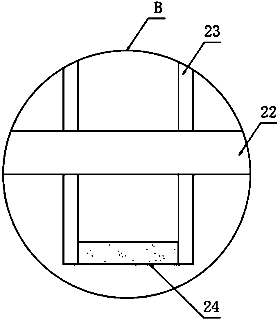
[0028] A dust discharge pipe 20 runs through the bottom of the annular outer cover 10, a first vacuum pump 21 is provided on the dust discharge pipe 20, a storage barrel 22 is provided on the side of the mounting seat 12, and the dust discharge pipe 20 runs through the storage tank. The top of the material tank 22 extends to the...
PUM
 Abstract
Description
Claims
Application Information
 - R&D Engineer
- R&D Manager
- IP Professional
- Industry Leading Data Capabilities
- Powerful AI technology
- Patent DNA Extraction
Browse by: Latest US Patents, China's latest patents, Technical Efficacy Thesaurus, Application Domain, Technology Topic, Popular Technical Reports.
© 2024 PatSnap. All rights reserved.Legal|Privacy policy|Modern Slavery Act Transparency Statement|Sitemap|About US| Contact US: help@patsnap.com


