
Pneumatic chemical pump

A chemical pump, pneumatic technology, applied in the field of pneumatic chemical pumps, can solve problems such as filling liquids, and achieve the effect of a wide range of use

Inactive Publication Date: 2018-11-06
ANHUI CHANGYU PUMP VALVE MFG CO LTD
View PDF4 Cites 0 Cited by
  • Summary
  • Abstract
  • Description
  • Claims
  • Application Information

AI Technical Summary

Problems solved by technology

[0003] When the existing chemical pumps are in use, the suction pipe and the pump must be filled with liquid, which is inconvenient during operation, especially when the chemical pump needs to be in a low well or workers cannot fill the suction pipe and pump with liquid. For workers in this technical field, it is necessary to design a chemical pump that can work under liquid

Method used


Image

  • Pneumatic chemical pump
  • Pneumatic chemical pump
  • Pneumatic chemical pump

Examples


Embodiment Construction

[0022] The following are specific embodiments of the present invention and the accompanying drawings to further describe the technical solutions of the present invention, but the present invention is not limited to these embodiments.

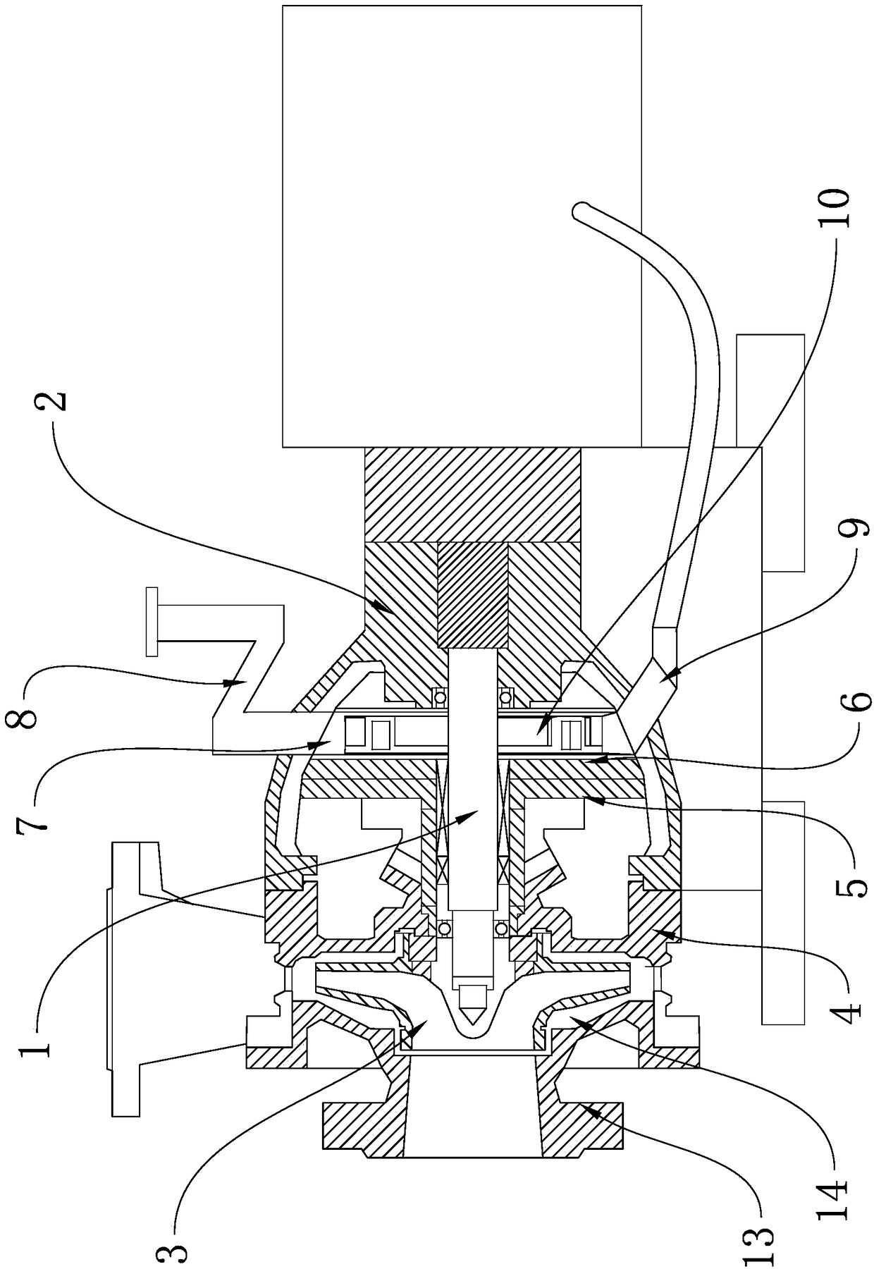
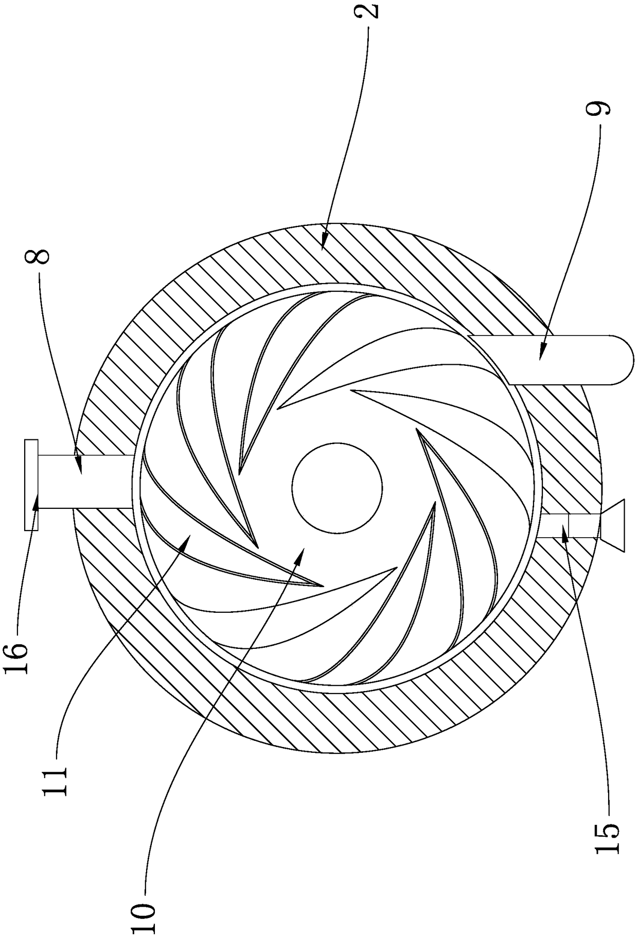
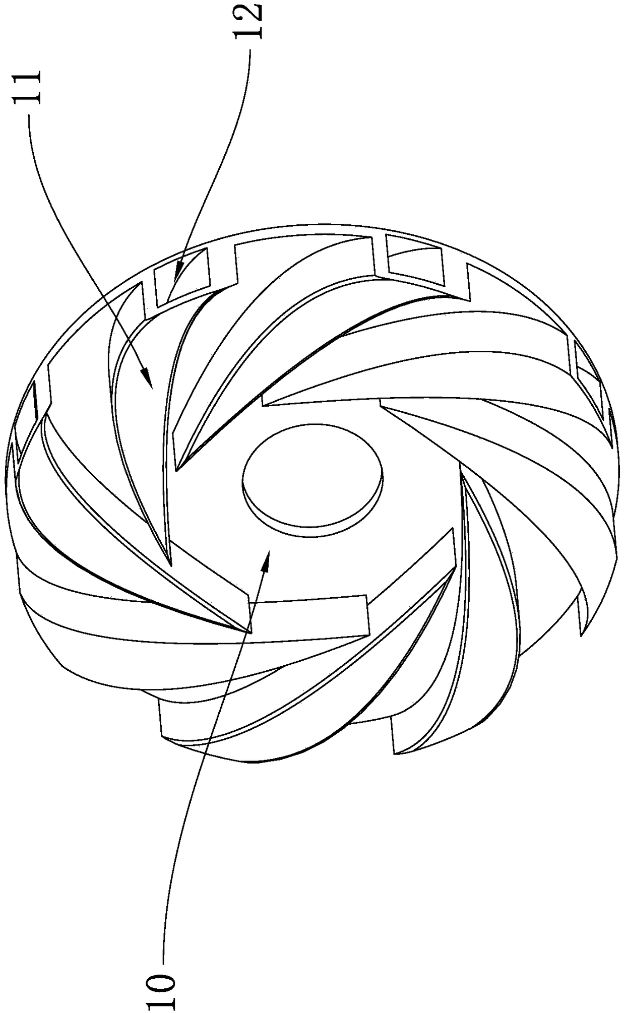
[0023] like Figure 1 to Figure 3 As shown, the pneumatic chemical pump includes a main shaft 1, a bracket 2 and an impeller 3. The impeller 3 is fixed on one end of the main shaft 1. Set in the bracket 2, the isolation sleeve 5 is fixed on the pump casing 4; the isolation sheet 6 is fixed on the isolation sleeve 5, and forms a closed chamber 7 with the bracket 2; the upper part of the bracket 2 is fixed with the cavity 7 The air outlet pipe 8 that communicates with each other, the lower part of the bracket 2 is fixed with an air intake pipe 9 that is communicated with the chamber 7, and the air inlet pipe 9 is connected to the air pump through the air pipe; The gas wheel 10 is made of fluoroplastic. The gas wheel 10 is provided with a pluralit...


PUM


Abstract

The invention provides a pneumatic chemical pump, belongs to the technical field of water pumps, and solves the technical problems of a traditional chemical pump incapable of normally working under liquid and the like. The pneumatic chemical pump comprises a main shaft, a bracket and an impeller; the impeller is fixedly arranged at one end of the main shaft; a pump shell, an isolation sleeve and an isolation piece sleeve the main shaft in sequence; the pump shell is fixedly arranged in the bracket; the isolation sleeve is fixedly arranged on the pump shell; the isolation piece is fixedly arranged on the isolation sleeve, and forms a closed cavity with the bracket; an exhaust pipe, communicating with the cavity, is fixedly arranged at the upper part of the bracket; an intake pipe, communicating with the cavity, is fixedly arranged at the lower part of the bracket; the intake pipe is connected with an air pump through an air pipe; an air wheel, positioned in the cavity, is fixedly arranged on the main shaft; the air wheel is provided with multiple wheel blades arranged around the axis at equal intervals; air storage cavities are formed in the wheel blades; the wheel blades are provided with intake ports communicating with the air storage cavity; and the intake ports are arranged on the peripheral surface of the air wheel. The pneumatic chemical pump has the advantage of normal operation under liquid.

Description

technical field [0001] The invention belongs to the technical field of water pumps, in particular to a pneumatic chemical pump. Background technique [0002] Before starting the pump, the suction line and the pump must be filled with liquid. After the pump is turned on, the impeller rotates at high speed, and the liquid in it rotates with the blades. Under the action of centrifugal force, it flies away from the impeller and is ejected outward. The ejected liquid gradually slows down in the diffusion chamber of the pump casing, and the pressure gradually increases. Outlet, the discharge pipe flows out. At this time, a vacuum low-pressure area with neither air nor liquid is formed at the center of the blade due to the liquid being thrown around. The liquid in the liquid pool flows into the pump through the suction pipe under the action of the atmospheric pressure on the pool surface, and the liquid is thus continuous. It is continuously sucked up from the liquid pool and con...

Claims


Application Information

Patent Timeline
IPC IPC(8): F04D13/04
CPCF04D13/04
Inventor 王爱军
Owner ANHUI CHANGYU PUMP VALVE MFG CO LTD
Learn More