
Photocatalytic device for production of gaseous hydrogen

A photocatalytic and hydrogen technology, applied in the direction of hydrogen production, metal/metal oxide/metal hydroxide catalyst, organic compound/hydride/coordination complex catalyst, etc., can solve the problem of energy balance and energy yield has not been optimized And other issues

Active Publication Date: 2018-11-09
H2WIN SA
View PDF4 Cites 2 Cited by
  • Summary
  • Abstract
  • Description
  • Claims
  • Application Information

AI Technical Summary

Problems solved by technology

Thus, since two different energy sources must be combined to produce hydrogen, one luminescent and the other electric, the overall energy balance and overall energy yield are not optimized

Method used


Image

  • Photocatalytic device for production of gaseous hydrogen
  • Photocatalytic device for production of gaseous hydrogen
  • Photocatalytic device for production of gaseous hydrogen

Examples


Embodiment Construction

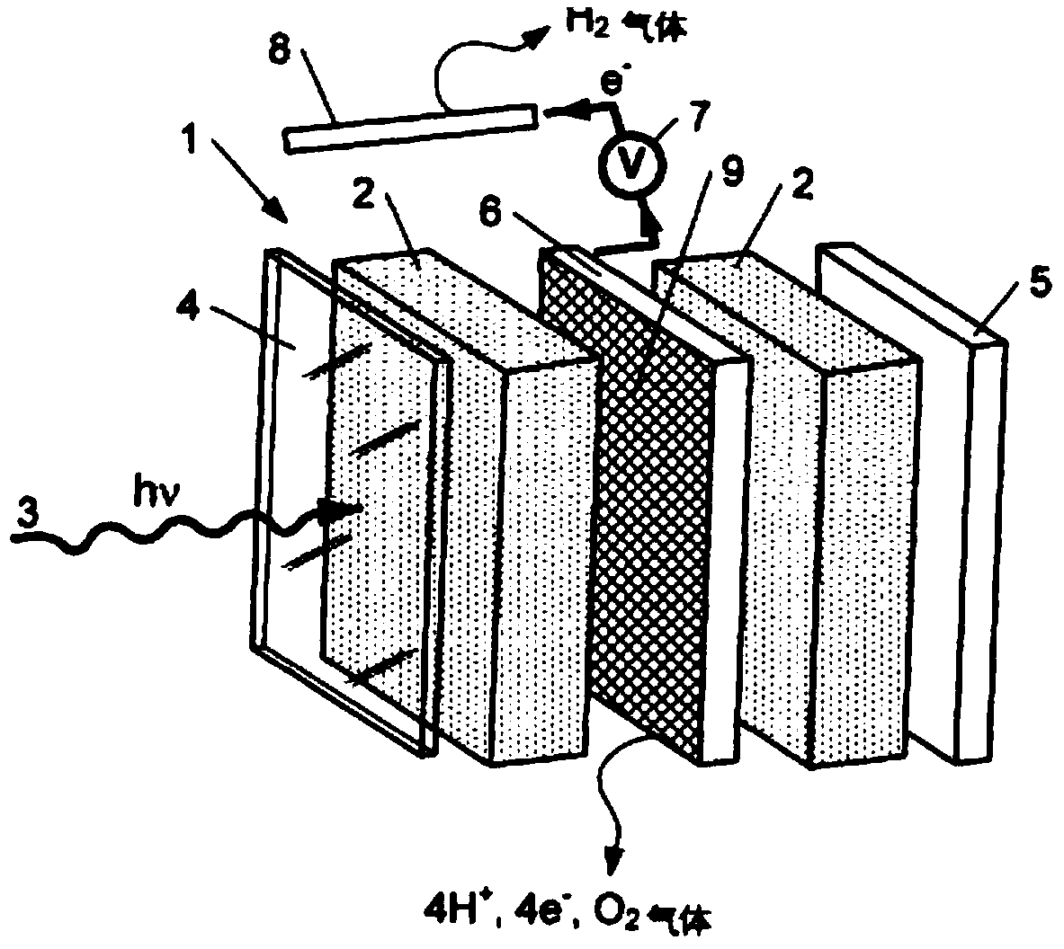
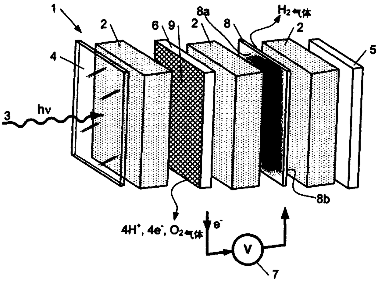
[0061] figure 1 Show the preparation of hydrogen (H) from water phase 2 and light source 3 in background technology 2 gas) device 1. The device 1 comprises a front wall 4 which allows the passage of photons from a light source 3 to illuminate a photocatalytic system 9 in contact with the aqueous phase 2 . The device also comprises a rear wall 5, eg made of a suitable polymer. Of course, the device 1 also includes top, bottom and side walls together with front and rear walls, forming a waterproof device (generator). For example, the front wall 4 may be made of glass, although any suitable material that enables photons from the light source 3 to illuminate the photocatalytic system 9 in contact with the aqueous phase 2 is encompassed by the invention.

[0062] The aqueous phase 2 soaks an anode 6 (such as a carbon anode 6 ) containing a photoenzyme, such as PSII as a photocatalytic system 9 , connected via a voltage regulator 7 to a cathode submerged in the same aqueous phase...


PUM


Abstract

The invention relates to a photocatalytic aqueous-phase-dissociation device for producing gaseous hydrogen, said device being arranged such that at least one photocatalytic system that is in contact with the aqueous phase can be irradiated by a light source in order to produce gaseous oxygen, electrons and protons by means of a reaction involving the oxidation of the aqueous phase at an electron capture means. The device comprises: a first zone containing the aqueous phase; and a proton reduction means arranged to perform a reaction involving the reduction of the protons with the electrons soas to produce gaseous hydrogen, said proton reduction means being a proton exchange interface having a front face oriented towards the electron capture means and a back face, in which only the back face of the proton exchange interface comprises at least one catalyst and / or at least one catalytic system.

Description

technical field [0001] The present invention relates to a photocatalytic device for decomposing an aqueous phase to produce hydrogen, the device shown being arranged in such a way that at least one photocatalytic system in contact with said aqueous phase can be irradiated by a light source through an oxidation reaction in said aqueous phase , producing oxygen, electrons and protons at an electron capture device comprising: [0002] a first zone comprising said aqueous phase, and [0003] means for reducing said protons by said electrons to perform said reduction reaction on said protons to produce hydrogen. Background technique [0004] In the present invention, the term "photocatalytic system" refers to a photocatalyst comprising at least one photo-enzyme and / or its coenzyme and any oxidation reaction in water phase. [0005] In the present invention, the term "aqueous phase" refers to a phase containing only water or any phase containing water and at least one additive, ...

Claims


Application Information

Patent Timeline
IPC IPC(8): B01J14/00B01J19/12C01B3/04C25B1/00C25B9/19C25B9/23
CPCB01J19/127C01B3/042C25B1/04C01B13/0207Y02E60/36C25B11/00C25B1/55C25B9/23C25B9/19C25B11/044B01J35/39B01J14/005B01J23/42B01J31/003
Inventor 菲利浦·劳热克莱尔·勒马克勒斯蒂芬妮·杰林娜塔莉·乔布法布里斯·弗兰克朱塞佩·卡尔达蕾拉巴特·格希尔斯达明·戈道克斯皮埃尔·卡尔多
Owner H2WIN SA
Learn More