Sewage treatment device

A sewage treatment device and sewage treatment system technology, applied in water/sewage treatment, water/sewage multi-stage treatment, biological water/sewage treatment, etc., can solve the complex structure of sewage treatment system, blockage of sewage treatment equipment, and expensive equipment investment and other problems, to achieve the effect of improving the filtering effect, low equipment investment, and low energy consumption

Inactive Publication Date: 2018-11-23
华蓥市职业教育培训中心
View PDF7 Cites 4 Cited by
  • Summary
  • Abstract
  • Description
  • Claims
  • Application Information

AI Technical Summary

Problems solved by technology

[0004] The object of the present invention is to solve the problems of complex structure of the above-mentioned sewage treatment system, expensive equipment investment, poor trea

Method used


Image

  • Sewage treatment device

Examples


Example Embodiment

[0025] Example 1

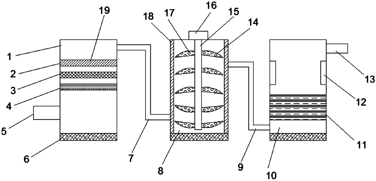
[0026] A sewage treatment device. The sewage treatment system includes a filter box 1, a mixing box 8, and a processing box 10 that are connected through from left to right. A water inlet pipe 5 is provided at the bottom of one side of the mixing box 8. A water outlet pipe 13 is provided at the top of one side of the filter box 1, the top of the filter box 1 is connected to the bottom of the mixing box 8 through the pipe one, and the top of the mixing box 8 is connected to the bottom of the processing box 10 through the pipe two 9. Connected, the filter box 1 is provided with a multi-stage filter screen between the water inlet pipe 5 and the pipe one 7, the stirring box 8 is provided with a stirrer, and the inner side wall of the stirring box 8 is provided with an activated carbon adsorption plate 18 A biological filler 11 is provided inside the processing box 10, and a slag discharge door 6 is provided at the bottom of the filter box 1, the stirring box 8, and...

Example Embodiment

[0028] Example 2

[0029] On the basis of Embodiment 1, the multi-stage filter screen is provided with at least two layers, and the size of the mesh 19 increases from top to bottom. By installing a multi-layer filter screen, the filtering effect of the filter tank on the sewage can be improved, thereby reducing the burden of the subsequent equipment on the sewage treatment, and improving the subsequent sewage treatment effect.

Example Embodiment

[0030] Example 3

[0031] On the basis of Example 2, the multi-stage filter is provided with three layers, from top to bottom, they are the first-level filter 2, the second-level filter 3, and the third-level filter 4. The mesh 19 is 0.5 to 1 cm, the mesh 19 of the secondary filter 3 is 1 to 2 cm, and the mesh 19 of the tertiary filter 4 is 2 to 4 cm. By setting up multi-stage filters with different mesh sizes 19, the impurities of different sizes in the sewage can be filtered. The impurities trapped by the multi-stage filters fall directly to the bottom of the filter tank by its own gravity, and then the slag gate 6 Impurities are discharged.


PUM


Abstract

The invention discloses a sewage treatment device. The sewage treatment device sequentially comprises a filtering box, a stirring box and a treatment box from left to right, wherein the filtering box,the stirring box and the treatment box are connected in a penetrating way; a water intake pipe is arranged at the bottom part of one side of the stirring box; a water drain pipe is arranged at the top part of one side of the treatment box; the top part of one side of the filtering box is communicated with the bottom part of one side of the stirring box through a pipeline I; the top part of one side of the stirring box is communicated with the bottom part of one side of the treatment box through a pipeline II; a plurality of stages of filtering nets are arranged in the filtering box and between the water intake pipe and the pipeline I; a stirrer is arranged in the stirring box; an activated carbon adsorption plate is arranged at the inside wall of the stirring box; a biological filler is arranged in the treatment box; slag discharge doors are respectively arranged at the bottom parts of the filtering box, the stirring box and the treatment box. The sewage treatment device can solve theproblems of the sewage treatment system that the structure is complicated, the equipment investment is high, the treatment effect is poor, the treatment efficiency is low, and the blockage is easy due to impurities in the sewage.

Description

technical field [0001] The invention belongs to the technical field of sewage treatment, and in particular relates to a sewage treatment device. Background technique [0002] Our country is facing a water resource crisis, and the task of sewage treatment is urgent and arduous. At present, the operation of sewage treatment plants in my country is not good, and excessive energy consumption is an important bottleneck restricting the development of sewage treatment industry. In recent years, the basic theory and treatment process of sewage treatment have become more and more mature, but the optimization control technology of sewage treatment process is still lagging behind. At present, the control level of sewage treatment plants in our country is relatively low, and most of them use simple PID control or manual control, and there is almost no application of optimal control methods. On the other hand, the management level of my country's sewage treatment plants is low, which a...

Claims


Application Information

Patent Timeline
IPC IPC(8): C02F9/14
CPCC02F1/001C02F1/281C02F1/283C02F3/00C02F9/00
Inventor 董建军
Owner 华蓥市职业教育培训中心
Why Eureka
Try Eureka