Supercharge Your Innovation With Domain-Expert AI Agents!

A wide band radio frequency circulator

A wide-band, circulator technology, applied in the field of passive radio frequency equipment, can solve problems such as poor RF signal transmission and reception

Inactive Publication Date: 2018-11-23
EAGANTU
View PDF7 Cites 1 Cited by
  • Summary
  • Abstract
  • Description
  • Claims
  • Application Information

AI Technical Summary

Problems solved by technology

As mentioned above, conventional RF circulators cannot meet this need
Also, insertion loss can lead to poor transmission and reception of RF signals

Method used


Image

  • A wide band radio frequency circulator
  • A wide band radio frequency circulator
  • A wide band radio frequency circulator

Examples


Embodiment Construction

[0026] It is important to note that the embodiments disclosed herein are only examples of the many advantageous uses of the innovative teachings herein. In general, statements made in the specification of the present application do not necessarily limit any of the claimed embodiments. Furthermore, some statements may apply to some inventive features but not to others. In general, unless stated otherwise, singular elements may be plural and vice versa without loss of generality. In the drawings, like reference numerals refer to like parts throughout the several views.

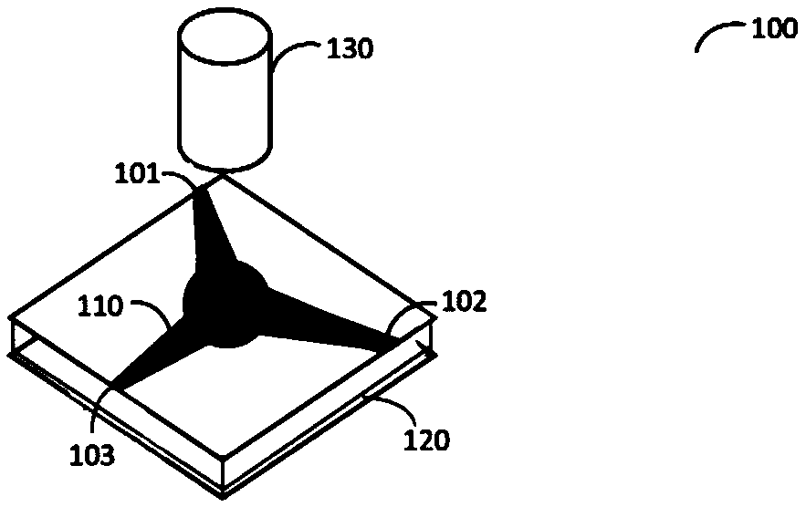
[0027] A broadband RF circulator is provided as an example of the disclosed embodiments. In one embodiment, the disclosed RF circulator provides a novel design with wide bandwidth, low insertion loss, high isolation and small physical size. The disclosed RF circulator can operate in full duplex mode. In an example embodiment, the disclosed RF circulator has a bandwidth between 1 GHz and 7 GHz in multiple dif...


PUM


Abstract

A wide band radio frequency (RF) circulator is presented. The RF circulator includes at least one stage having four ports, a first end, and a second end, wherein a first port and a third port are connected at the first end of the at least one stage, a second port and a fourth port are connected at the second end of the at least one stage, and each of the at least one stage includes a pair of couplers connected through a first delay line and a second delay line, thereby forming a network of couplers in the at least one stage.

Description

[0001] Cross References to Related Applications [0002] This application claims the benefit of U.S. Provisional Application No. 62 / 323,814, filed April 18, 2016, and U.S. Provisional Application No. 62 / 360,398, filed July 10, 2016, the contents of which are hereby incorporated by reference. technical field [0003] The present disclosure relates generally to passive radio frequency (RF) devices, and more particularly to broadband radio frequency (RF) circulators. Background technique [0004] An RF circulator is a 3-port ferromagnetic passive device used to condition signal flow within a circuit. RF circulators transmit the incoming signal in one direction. An example structure of a conventional RF circulator 100 is shown in FIG. 1 . [0005] A conventional RF circulator 100 includes a Y-shaped conductor (eg, metal strip) 110 placed on a ferrite substrate 120 and a permanent magnet 130 orthogonal to the Y-shaped conductor 110 . An RF signal input at port 101 is transmitt...

Claims


Application Information

Patent Timeline
Patent Type & Authority Applications(China)
IPC IPC(8): H01P1/38
CPCH01P1/387H01P1/397H01P5/184H01P9/00H04B1/40H03H7/004
Inventor M·达希亚E·沙凯迪
Owner EAGANTU
Features
  • R&D
  • Intellectual Property
  • Life Sciences
  • Materials
  • Tech Scout
  • Unparalleled Data Quality
  • Higher Quality Content
  • 60% Fewer Hallucinations
Learn More