Coil and electronic equipment

A coil and main coil technology, applied in the direction of circuits, transformers/inductor coils/windings/connections, electrical components, etc., can solve problems such as limited coil thickness, increase cross-sectional area, increase Q value, and suppress skin effect of effect

Active Publication Date: 2018-11-30
SHANGHAI AMPHENOL AIRWAVE COMM ELECTRONICS
View PDF6 Cites 2 Cited by
  • Summary
  • Abstract
  • Description
  • Claims
  • Application Information

AI Technical Summary

Problems solved by technology

However, due to cost or space, the thickness of the coil is limited, and the Q

Method used


Image

  • Coil and electronic equipment
  • Coil and electronic equipment
  • Coil and electronic equipment

Examples


Example Embodiment

[0047] Example 1

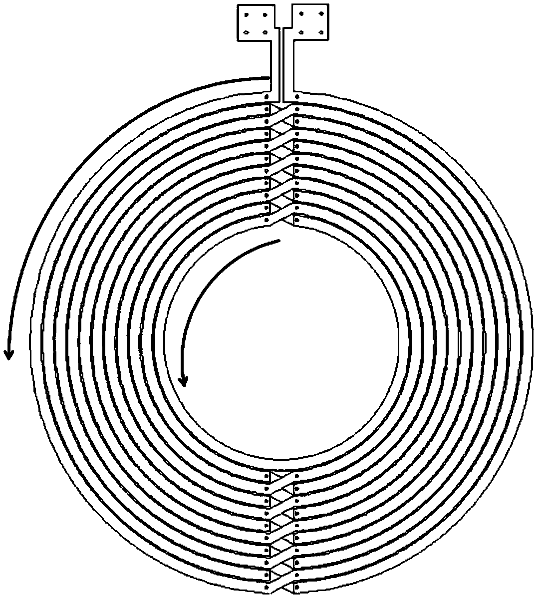
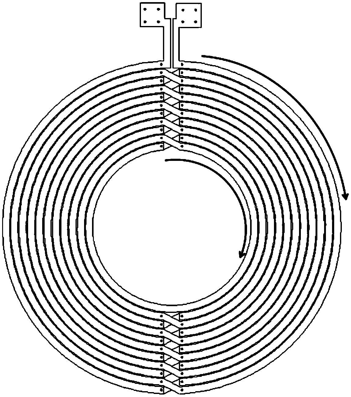
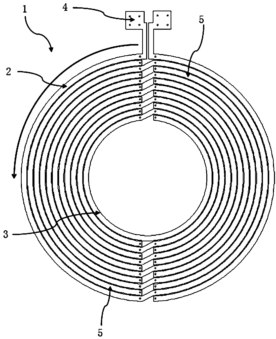
[0048] See figure 1 , figure 2 , image 3 as well as Figure 4 , A coil, including multiple coil layers and insulating layers, the current direction in the wiring of the multilayer coil layers is the same; the multilayer coil layers include at least the first coil layer 1 and the second coil layer 6; the insulating layer is arranged in the phase Between adjacent coil layers; the first coil layer 1 includes a first main coil 2 wound from the outer ring to the inner ring, and the second coil layer 6 includes a second main coil 7 wound from the inner ring to the outer ring; The inner coil wire 3 of a main coil 2 and the inner coil wire 8 of the second main coil 7 are connected in parallel; the coil wires of the first main coil 2 except for the inner wire 3 and the second main coil 7 except for The coil wires other than the inner coil wire 8 are alternately wound; the outer coil end 4 of the first main coil 2 and the outer coil end 9 of the second main coil 7 are ...

Example Embodiment

[0052] Example 2

[0053] On the basis of embodiment 1, this embodiment is further improved. The coil also includes a third coil layer, the third coil layer is arranged on the side of the first coil layer 1, the third coil layer and the first coil layer 1 An insulating layer is provided between; or, the third coil layer is provided on the side of the second coil layer 6, and an insulating layer is provided between the third coil layer and the second coil layer 6; the third coil layer includes The third main coil of the inner circle, the inner circle trace of the third main coil and the inner circle trace 3 of the first main coil 2 and the inner circle trace 8 of the second main coil 7 are connected in parallel; the third main coil is in addition to it The coil routing other than the coil routing corresponds to the coil routing position of the first main coil 2 except its inner coil routing 3; the outer coil end of the third main coil and the outer coil of the first main coil 2 T...

Example Embodiment

[0060] Example 3

[0061] An electronic device includes the coil in any one of the above embodiments.


PUM


Abstract

The invention discloses a coil, which comprises a plurality of coil layers and insulating layers, wherein the coil layers at least comprise a first coil layer and a second coil layer; the insulating layers are arranged between adjacent coil layers; the first coil layer comprises a first primary coil wound from the outer circle to the inner circle, and the second coil layer comprises a second primary coil wound from the inner circle to the outer circle; coil traces of the first primary coil and the coil traces of the second primary coil are alternately wound; the outer circle end of the first primary coil and the outer circle end of the second primary coil are connected with an external electric signal receiving unit; the first coil layer further comprises a first secondary coil corresponding to the traces of the second primary coil; and the second coil layer further comprises a second secondary coil corresponding to the traces of the first primary coil. The coil and electronic equipment can obtain higher quality factors in limited space.

Description

Technical field [0001] The invention belongs to the field of coil structure design, and in particular relates to a coil and electronic equipment. Background technique [0002] Inductance coils are more and more commonly used in electronic devices, especially in some new applications, such as NFC (Near Field Communication), wireless charging, etc. The Q value of the coil, also called the quality factor, is the main parameter for evaluating the coil. The higher the Q value of the coil, the smaller its loss and the higher the efficiency. [0003] The working frequency of the existing wireless charging coil is relatively high, and the Q value of the coil is relatively high. However, due to cost or space, the thickness of the coil is limited, and the Q value of the coil can only be increased as much as possible in a limited space. Summary of the invention [0004] The technical problem to be solved by the present invention is to provide a coil and an electronic device, which can obtain...

Claims


Application Information

Patent Timeline
IPC IPC(8): H01F27/28
CPCH01F27/28H01F27/2823H01F27/2828
Inventor 何大伟吴涛
Owner SHANGHAI AMPHENOL AIRWAVE COMM ELECTRONICS
Why Eureka
Try Eureka