Pressure foot device for sewing machine

A sewing machine presser foot and presser plate technology, which is applied in the direction of sewing machine components, sewing equipment, cloth pressing mechanism, etc., can solve troubles, surpass problems such as manual sewing, and achieve the effects of convenient use, improved work efficiency, and easy pressing

Inactive Publication Date: 2018-12-07
SUZHOU KAICHENG SEWING EQUIP
View PDF0 Cites 1 Cited by
  • Summary
  • Abstract
  • Description
  • Claims
  • Application Information

AI Technical Summary

Problems solved by technology

And derived art forms such as hand-push embroidery and computer embroidery. There are many classification methods of sewing machines. The more common ones are distinguished by stitches and uses. Type stitch is the most common. It consists of two sutures, which are intertwined like twisted ropes. The interweaving point is in the middle of the sewing material. From the cross-section of the stitches, the two sutures are like two locks interlocking each other. Therefore, it is called a lock stitch, which is used in sewing materials such as cotton, wool fabric or leather with a small shrinkage rate. The front and back sides have the same shape, just like a dotted line. Sewing, the sewing machine presser foot is an essential part of the feeding mechanism of the sewing machine. The sewing machine presser foot plays a very important role in the production process, such as special sewing machine presser feet for top thread and hidden zippers, and pleated sewing machines Presser foot, etc., the presser foot is mostly controlled manually during use, which is more troublesome

Method used


Image

  • Pressure foot device for sewing machine
  • Pressure foot device for sewing machine
  • Pressure foot device for sewing machine

Examples


Embodiment Construction

[0018] The preferred embodiments of the present invention will be described below in conjunction with the accompanying drawings. It should be understood that the preferred embodiments described here are only used to illustrate and explain the present invention, and are not intended to limit the present invention.

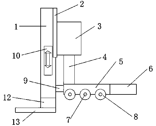
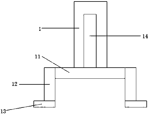
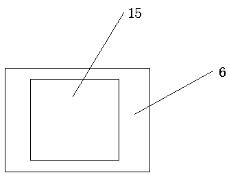
[0019] like Figure 1-4 As shown, a sewing machine presser foot device includes a vertical plate 1, the right end of the vertical plate 1 is fixedly connected with a fixed plate 2, and an electric push rod 3 is fixedly installed on the fixed plate 2, and the electric push rod is moved through the fixed plate 2. 3 is fixedly connected to the vertical plate 1, the telescopic rod 4 is installed on the electric push rod 3, and the bottom end of the telescopic rod 4 is fixedly connected with the presser foot plate 5, and the electric push rod 3 drives the telescopic rod 4 to move downward and hold down Cloth, compared with traditional manual control, is more labor-saving...


PUM


Abstract

The invention relates to a pressure foot device for a sewing machine. The device comprises a vertical plate, a fixing plate is fixedly connected to the right end of the vertical plate, and an electricpush rod is fixedly installed on the fixing plate; a retractable rod is installed on the electric push rod, a pressure foot plate is fixedly connected to the bottom of the retractable rod, and a working plate is fixedly connected to the right end of the pressure foot plate; a rectangular through hole is formed in the working plate, pressure foot idler wheels are movably connected to the bottom ofthe pressure foot plate through rotation shafts, and a connection rod is fixedly connected to the left end of the pressure foot plate; a slide block is fixedly connected to the left end of the connection rod, a slide groove is formed in the right end face of the vertical plate, and a first supporting plate is fixedly connected to the bottom of the vertical plate; second supporting plates are fixedly connected to the two ends of the first supporting plate respectively, mounting bases are fixedly connected to the bottoms of the second supporting plates, and a control switch is further arrangedon the vertical plate and connected with the electric push rod through a wire. The whole device is convenient to use, cloth is conveniently pressed and conveyed, and the working efficiency of the sewing machine is improved.

Description

technical field [0001] The invention relates to a sewing machine presser foot device, which belongs to the field of sewing equipment. Background technique [0002] A sewing machine is a machine that uses sewing thread to sew one or more layers of sewing materials together. The sewing machine can sew fabrics such as cotton, linen, silk, wool, and artificial fibers and products such as leather, plastic, and paper. Neat and beautiful, flat and firm, fast sewing speed and easy to use. And derived art forms such as hand-push embroidery and computer embroidery. There are many classification methods of sewing machines. The more common ones are distinguished by stitches and uses. Type stitch is the most common. It consists of two sutures, which are intertwined like twisted ropes. The interweaving point is in the middle of the sewing material. From the cross-section of the stitches, the two sutures are like two locks interlocking each other. Therefore, it is called a lock stitch, w...

Claims


Application Information

Patent Timeline
Patent Type & Authority Applications(China)
IPC IPC(8): D05B29/02D05B29/10D05B27/00
CPCD05B27/00D05B29/02D05B29/10
Inventor 季锴
Owner SUZHOU KAICHENG SEWING EQUIP
Why Eureka
Try Eureka