Check patentability & draft patents in minutes with Patsnap Eureka AI!

High-stability fingerprint module test device

A fingerprint module and testing device technology, which is applied in measuring devices, environmental/reliability testing, measuring electricity, etc., can solve the problem of unstable force applied on the product surface, affecting the reliability of product testing, and limited adjustable range, etc. problems, achieve consistent test results, save manpower, and increase productivity

Inactive Publication Date: 2018-12-07
JIANGSU A KERR BIOLOGICAL RECOGNITION TECH CO LTD
View PDF4 Cites 0 Cited by
  • Summary
  • Abstract
  • Description
  • Claims
  • Application Information

AI Technical Summary

Problems solved by technology

[0003] Therefore, this also brings opportunities and challenges to fingerprint module packaging companies. How to improve product performance and production efficiency is what they need to care about. In each process of fingerprint module packaging, fingerprint module functional testing is very critical. Now Existing technologies are pneumatic and pressure rod pressure methods. Due to the problems of these two pressure fixtures, the force exerted by the test pressure head connected to them on the product surface is unstable, which affects the reliability of product testing. Although the above One advantage of the pressure application method is that the pressure value is adjustable, but the adjustable range is limited. For example, the pneumatic pressure application method is difficult to provide low pressure. Therefore, when improving the pressure application method in the test device, a better solution The scheme should not only take into account the improvement of test stability, but also make the pressure easy to adjust

Method used


Image

  • High-stability fingerprint module test device
  • High-stability fingerprint module test device
  • High-stability fingerprint module test device

Examples


Embodiment 1

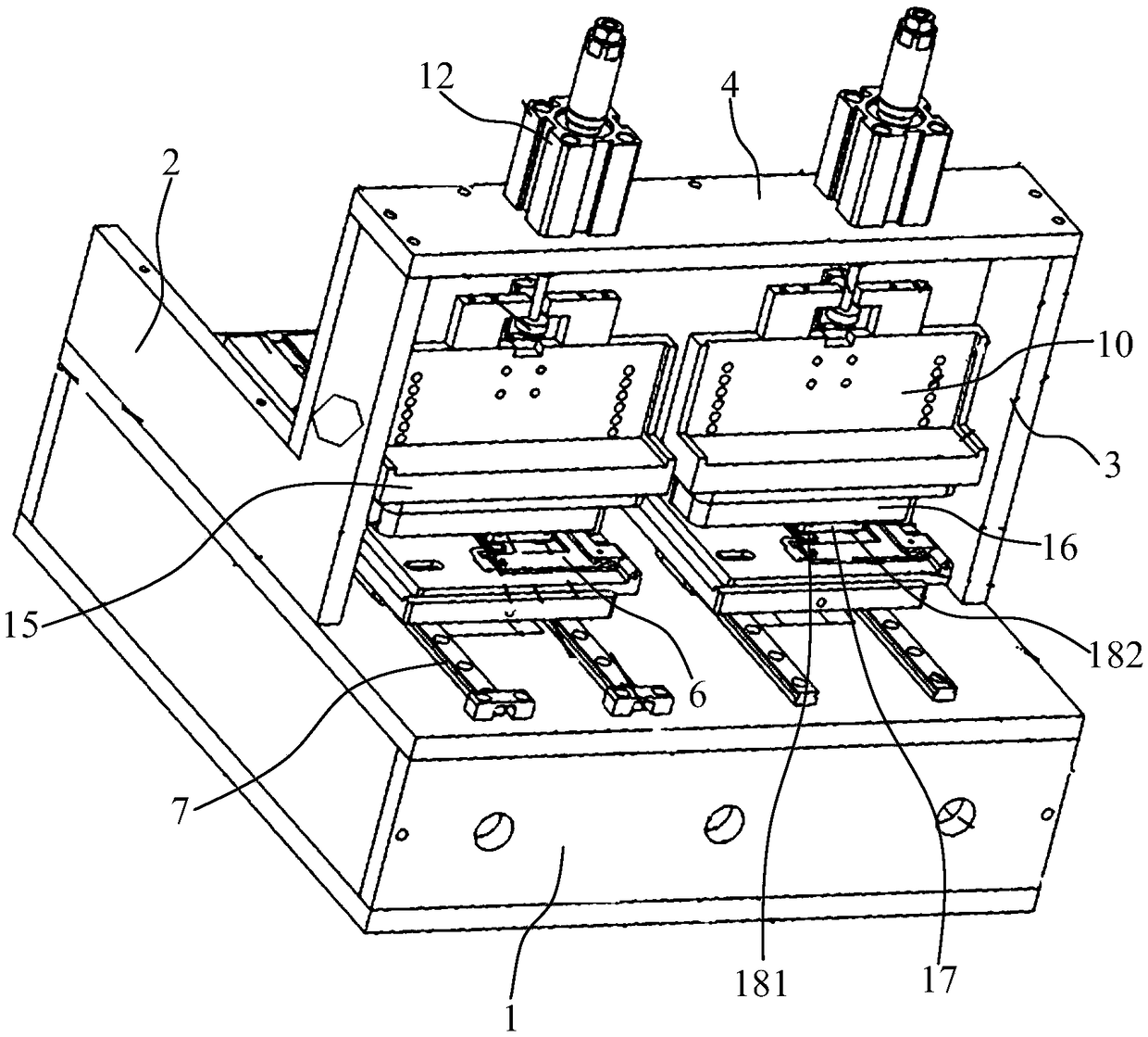
[0018] Embodiment 1: A high-stability fingerprint module testing device, including a base 1, a left support plate 2, a right support plate 3, a horizontal bridge plate 4, at least one horizontal stage 5 and a horizontal stage 5 The adapter plate 6 on the top, the left support plate 2 and the right support plate 3 are installed on the left and right sides of the base 1, the upper ends of the left support plate 2 and the right support plate 3 are fixed with the Horizontal bridge plate 4;

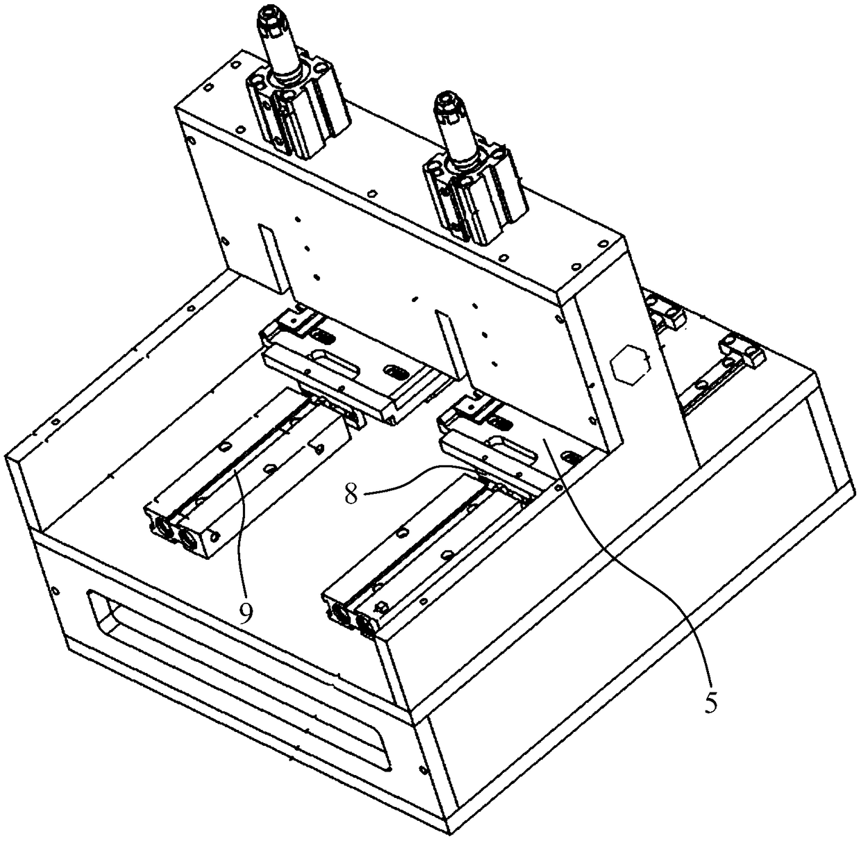
[0019] Two x-direction rails 7 are arranged in parallel on the surface of the base 1, and at least two x-direction sliders 8 are fixed on the lower surface of the horizontal stage 5 in parallel, and the x-direction rails 7 are embedded in the x-direction slide In the groove of the block 8, an x-direction drive mechanism 9 is located between the two x-direction rails 7 and below the horizontal stage 5;

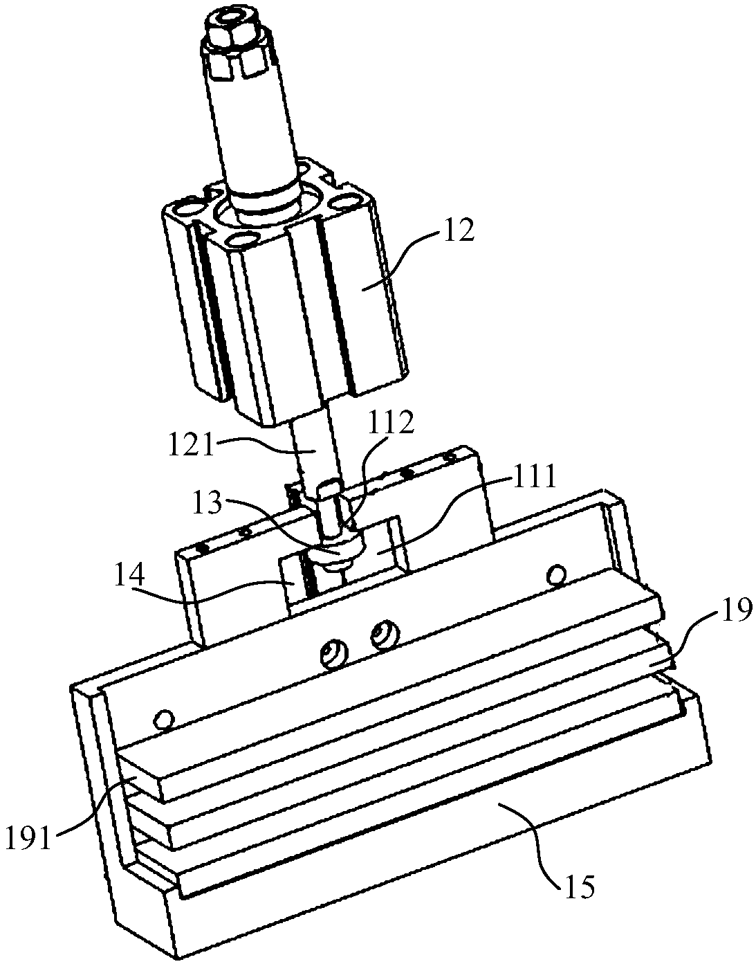
[0020] At least one lifting plate 10 is located between the horizontal bridge plate 4 and ...

Embodiment 2

[0024] Embodiment 2: A high-stability fingerprint module testing device, including a base 1, a left support plate 2, a right support plate 3, a horizontal bridge plate 4, at least one horizontal stage 5 and a horizontal stage 5 The adapter plate 6 on the top, the left support plate 2 and the right support plate 3 are installed on the left and right sides of the base 1, the upper ends of the left support plate 2 and the right support plate 3 are fixed with the Horizontal bridge plate 4;

[0025] Two x-direction rails 7 are arranged in parallel on the surface of the base 1, and at least two x-direction sliders 8 are fixed on the lower surface of the horizontal stage 5 in parallel, and the x-direction rails 7 are embedded in the x-direction slide In the groove of the block 8, an x-direction drive mechanism 9 is located between the two x-direction rails 7 and below the horizontal stage 5;

[0026] At least one lifting plate 10 is located between the horizontal bridge plate 4 and ...


PUM


Abstract

The invention discloses a high-stability fingerprint module test device, comprising a base, a left support plate, a right support plate, a horizontal bridge plate, at least one horizontal objective table, and an adapter plate mounted on the horizontal objective table. The horizontal bridge plate is fixed between the upper end of the left support plate and the upper end of the right support plate.At least one lifting plate is located between the horizontal bridge plate and the horizontal objective table. The upper end of the lifting plate has an inverted T-shaped through hole composed of a communicating hole and a rectangular through hole which communicate with each other. A hanging plate is mounted on the front end surface of the lifting plate. A plastic cavity box is mounted on the lowerend surface of the hanging plate. A left cylinder, a right cylinder and a test pressure head seat are arranged in the cavity of the plastic cavity box. A test pressure head for detecting the electrical performance of the fingerprint module is fixed to the test pressure head seat. The high-stability fingerprint module test device can adjust and control the force applied to the surface of a product, and can test various types of products. After repeated verification, the test device equipped with a pressure-applying tool has high stability, and consistent test results.

Description

technical field [0001] The invention relates to a testing device, in particular to a high-stability fingerprint module testing device. Background technique [0002] With the development of electronic technology, there are more and more functional and user-friendly mobile devices. For example, Apple installed a fingerprint recognition chip on the main button of Iphone5s for the first time, which brought users a convenient and fast body feeling. Since then, it has been equipped with fingerprint recognition chips. Functional mobile phones have become the basis for the public to choose mobile phones, and other brands of mobile phone manufacturers have also equipped their mobile phones with fingerprint locks. [0003] Therefore, this also brings opportunities and challenges to fingerprint module packaging companies. How to improve product performance and production efficiency is what they need to care about. In each process of fingerprint module packaging, fingerprint module func...

Claims


Application Information

Patent Timeline
Patent Type & Authority Applications(China)
IPC IPC(8): G01R31/00
CPCG01R31/003
Inventor 王丽张成位贤龙陈松姚燕杰
Owner JIANGSU A KERR BIOLOGICAL RECOGNITION TECH CO LTD
Features
  • R&D
  • Intellectual Property
  • Life Sciences
  • Materials
  • Tech Scout
  • Unparalleled Data Quality
  • Higher Quality Content
  • 60% Fewer Hallucinations
Learn More