Supercharge Your Innovation With Domain-Expert AI Agents!

Multi-level stamping die for cold stamping machining

A stamping die and cold stamping technology, applied in the field of multi-stage stamping dies, can solve the problems of increasing equipment costs, affecting the production efficiency of enterprises, and limiting the scope of use of stamping dies.

Inactive Publication Date: 2018-12-11
刘赞
View PDF5 Cites 0 Cited by
  • Summary
  • Abstract
  • Description
  • Claims
  • Application Information

AI Technical Summary

Problems solved by technology

[0003] The stamping die only relies on the press of the stamping device to pressurize the material to deform the material has certain limitations. It is powerless to produce some materials that exceed the pressure range of the press, thus limiting the use of the stamping die. Replace the press at this time It needs to increase the cost of equipment and affect the production efficiency of the enterprise. Therefore, there is an urgent need for a stamping die with a simple structure and economical use to increase the pressure range of the press.

Method used


Image

  • Multi-level stamping die for cold stamping machining
  • Multi-level stamping die for cold stamping machining
  • Multi-level stamping die for cold stamping machining

Examples


Embodiment 1

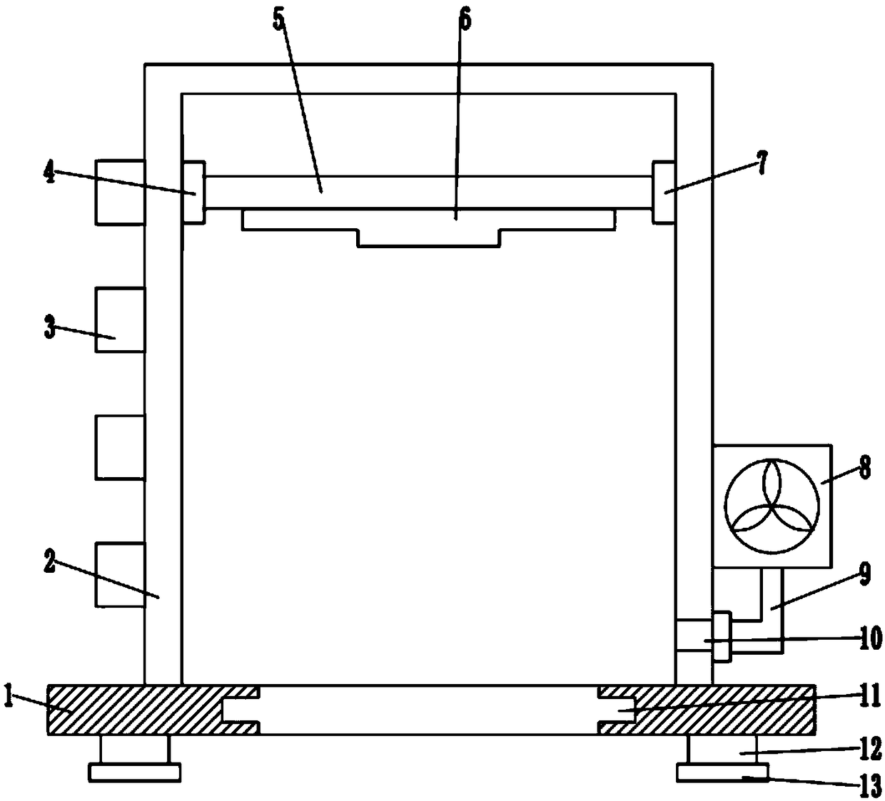
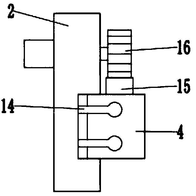
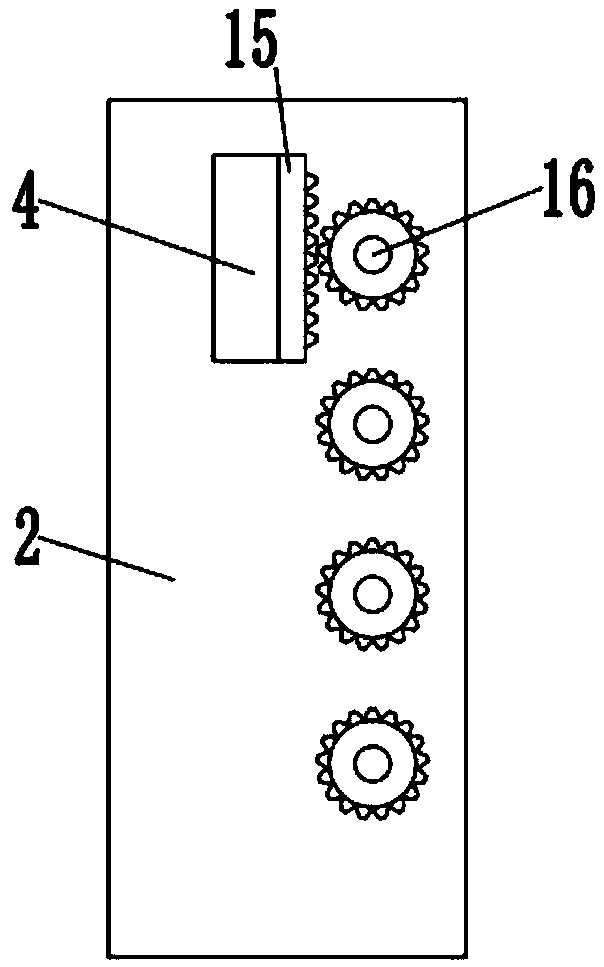
[0024] see Figure 1~3 , in an embodiment of the present invention, a multi-stage stamping die for cold stamping, including a base 1; a frame 2 is fixedly installed on the base 1, the frame 2 is an inverted U-shaped structure, and the inside of the frame 2 A lifting plate 5 is provided, and the inside of the frame 2 is located on the left and right sides of the lifting plate 5, and two chutes are symmetrically opened, and the left and right ends of the frame 2 are slidably installed by the first slider 4 and the second slider 7 respectively. In the inside of the frame 2; two guide rods 14 are symmetrically fixedly installed inside the chute, and the guide rod 14 is a long strip structure composed of a long bar and a cylinder. The first slide block 4 and the second slide block 7. There are guide grooves compatible with the guide rods 14 inside, so that the lifting plate 5 can slide up and down stably inside the chute; the bottom of the lifting plate 5 is fixedly equipped with a...

Embodiment 2

[0028] see Figure 1~4 , in an embodiment of the present invention, a multi-stage stamping die for cold stamping, including a base 1; a frame 2 is fixedly installed on the base 1, the frame 2 is an inverted U-shaped structure, and the inside of the frame 2 A lifting plate 5 is provided, and the inside of the frame 2 is located on the left and right sides of the lifting plate 5, and two chutes are symmetrically opened, and the left and right ends of the frame 2 are slidably installed by the first slider 4 and the second slider 7 respectively. In the inside of the frame 2; two guide rods 14 are symmetrically fixedly installed inside the chute, and the guide rod 14 is a long strip structure composed of a long bar and a cylinder. The first slide block 4 and the second slide block 7. There are guide grooves compatible with the guide rods 14 inside, so that the lifting plate 5 can slide up and down stably inside the chute; the bottom of the lifting plate 5 is fixedly equipped with a...


PUM


Abstract

The invention discloses a multi-level stamping die for cold stamping machining. The multi-level stamping die comprises a base fixedly provided with a machine frame. A lifting plate is arranged in themachine frame. The left end and the right end of the machine frame are arranged in the machine frame through a first sliding block and a second sliding block in a sliding manner. A stamping device isfixedly arranged at the bottom of the lifting plate. A containing groove facilitating material containing is formed in the middle position of the base, a rack is fixedly arranged on the rear side of the first sliding block, and the part, located on the rear side of the rack, of the left side of the machine frame is evenly and fixedly provided with a plurality of circular gears from top to bottom.During stamping manufacturing, when the small stamping force needs to be provided, a drive motor located at the bottom works, and accordingly, the bottom circular gear drives the lifting plate to ascend by a small section of distance. When the needed stamping force is gradually increased, motors on the machine frame sequentially start to work from bottom to top, and accordingly the circular gearsare used for elevating the lifting plate to the proper distance so that stamping can be conducted.

Description

technical field [0001] The invention relates to a stamping die, in particular to a multi-stage stamping die for cold stamping. Background technique [0002] Stamping die is a special process equipment for processing materials (metal or non-metal) into parts (or semi-finished products) in cold stamping processing, called cold stamping die (commonly known as cold stamping die). Stamping is a pressure processing method that uses a mold installed on a press to apply pressure to a material at room temperature to cause separation or plastic deformation to obtain the required parts. The materials for making stamping dies include steel, hard alloy, steel-bonded hard alloy, zinc-based alloy, low melting point alloy, aluminum bronze, polymer material and so on. The mold industry has been developing rapidly at a growth rate of about 15%, and the ownership of the mold industry has also undergone tremendous changes. In addition to state-owned professional mold factories, collectives, jo...

Claims


Application Information

Patent Timeline
IPC IPC(8): B21D37/10
CPCB21D37/10
Inventor 刘赞
Owner 刘赞
Features
  • R&D
  • Intellectual Property
  • Life Sciences
  • Materials
  • Tech Scout
  • Unparalleled Data Quality
  • Higher Quality Content
  • 60% Fewer Hallucinations
Learn More