Chemical engineering device for secondary hydration of phosphoric acid
A chemical equipment, phosphoric acid two technology, applied in the field of phosphoric acid, can solve the problems of difficulty in obtaining partial phosphoric acid, high temperature, etc., and achieve the effect of significant heat exchange effect and high heat exchange effect
- Summary
- Abstract
- Description
- Claims
- Application Information
AI Technical Summary
Problems solved by technology
Method used
Image

Examples
Embodiment 1
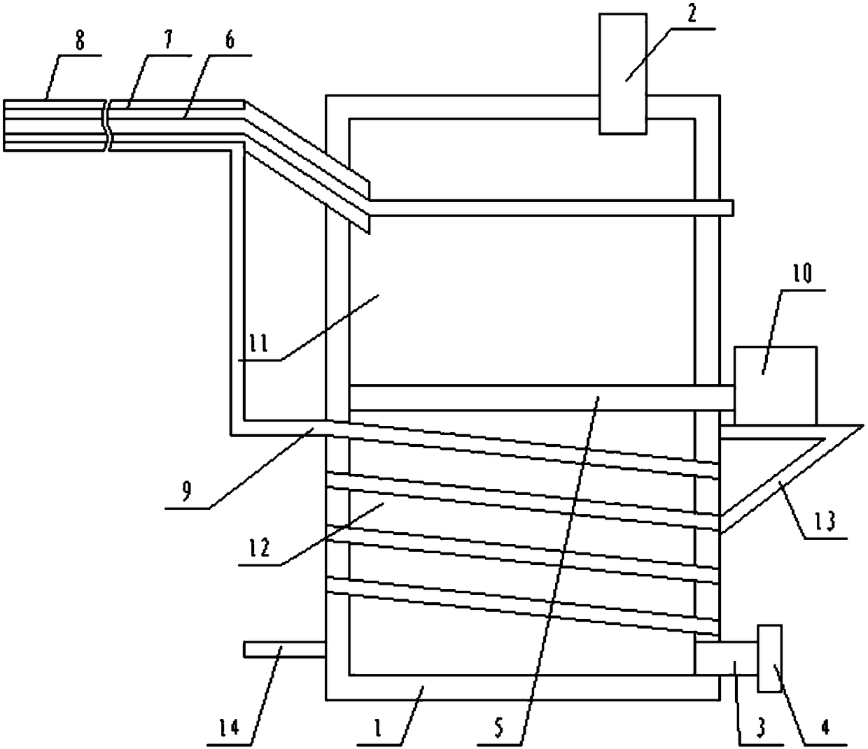
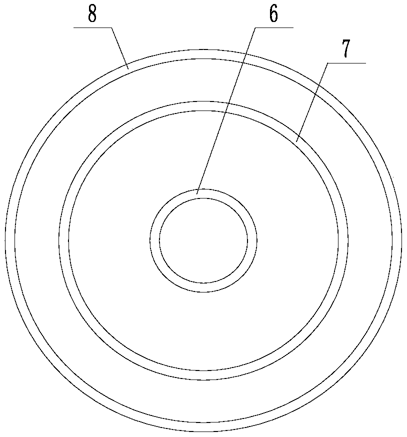
[0018] like figure 1 and figure 2 The chemical equipment shown for the secondary hydration of phosphoric acid includes a hydration tower 1, a water inlet pipe 2 and a water outlet pipe 3 that are communicated with the hydration tower 1, a plug 4 is provided on the water outlet pipe 3, and the water inlet pipe is 2 is located at the top of the hydration tower 1, the water outlet pipe 3 is located at the bottom of the hydration tower 1, and a gate valve 5 is arranged inside the hydration tower 1, and when the gate valve 5 is closed, the interior of the hydration tower 1 is divided into upper, The lower two parts, wherein the space above the gate valve 5 is the primary hydration chamber 11, and the space below the gate valve 5 is the secondary hydration chamber 12; it also includes a gas delivery pipe, which includes a diameter from the inside to the outside. The first metal tube 6, the second metal tube 7, and the ceramic tube 8 are distributed in the direction. The first meta...
Embodiment 2
[0020] like figure 1 and figure 2The chemical equipment shown for the secondary hydration of phosphoric acid, on the basis of the embodiment, the gas pipeline includes a horizontal section and an inclined section that are connected in turn, and the inclined section is from one end of the horizontal section to the primary hydration chamber 11. The direction slopes down. The circulation port 9 is located at the end connecting the horizontal section and the inclined section, and the annular space between the second metal tube 7 and the ceramic tube 8 is blocked at the end connecting the horizontal section and the inclined section. The gate valve 5 is a pneumatic gate valve, and the cylinder 10 of the pneumatic gate valve is fixed on a mounting bracket 13 , and the mounting bracket 13 is fixed on the outer side wall of the hydration tower 1 . The guide tube 9 is a metal corrugated hose.
PUM
 Abstract
Description
Claims
Application Information
 - R&D
- Intellectual Property
- Life Sciences
- Materials
- Tech Scout
- Unparalleled Data Quality
- Higher Quality Content
- 60% Fewer Hallucinations
Browse by: Latest US Patents, China's latest patents, Technical Efficacy Thesaurus, Application Domain, Technology Topic, Popular Technical Reports.
© 2025 PatSnap. All rights reserved.Legal|Privacy policy|Modern Slavery Act Transparency Statement|Sitemap|About US| Contact US: help@patsnap.com