[0020] In order to make the technical means, creative features, objectives and effects of the present invention easy to understand, the present invention will be further explained below in conjunction with specific embodiments.
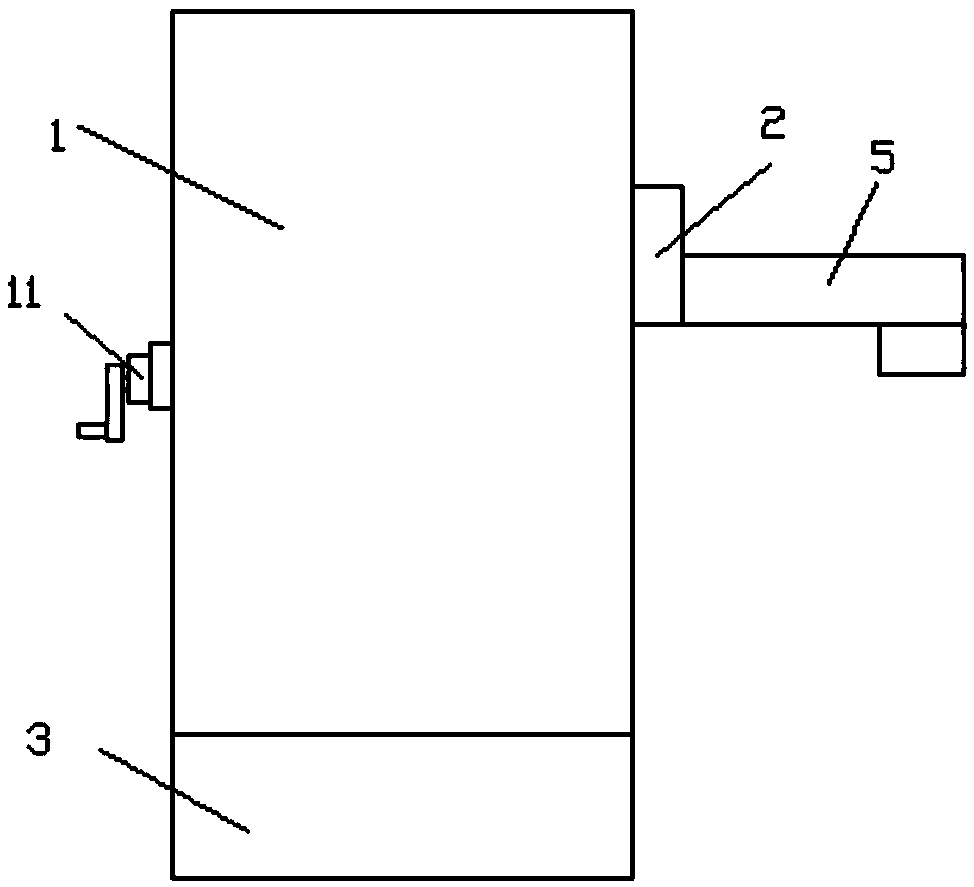
[0021] Such as Figure 1 to Figure 6 As shown, a height-adjustable portable water purifier is characterized in that it comprises a main body 1, a card plate 3 is fixedly connected to the bottom of the main body 1, a hand rocker 11 is provided on the left side wall of the main body 1, and the right side of the main body 1 The side wall is provided with a sliding block 2, the sliding block 2 is provided with a water outlet 5, and the sliding block 2 is slidingly connected with the side wall of the main body 1.
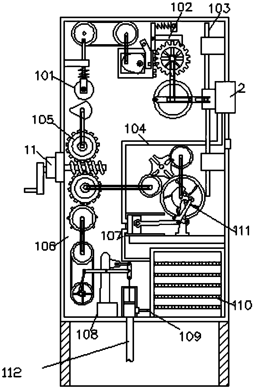
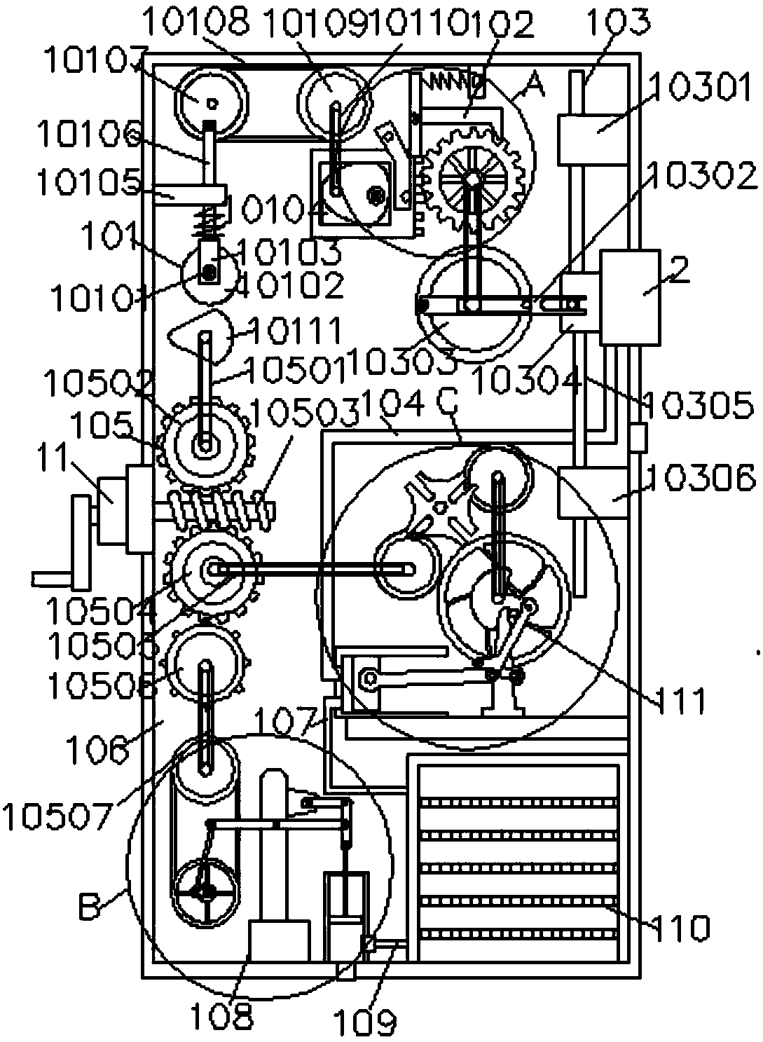
[0022] The main body includes a cam transmission device 101, a height adjustment device drive mechanism 102, a height adjustment device 103, a water pumping pipe 104, a hand crank drive device 105, a housing 106, a water pumping pipe 107, a water pumping device 108, and a water inlet pipe 109, The filter device 110, the drainage device 111, and the pumping pipe 112 are composed. The inner surface of the housing 106 is provided with a hand crank drive device 105, and the upper end surface of the hand crank drive device 105 is connected with a cam transmission device 101. The height adjustment device drive mechanism 102 is connected to the other end of the cam transmission device 101, the water pumping device 108 is connected to the lower end surface of the hand crank drive device 105, and the water pumping device 108 is connected to the filter device 110 through a water inlet pipe 109, The drainage device 111 is connected to the filtering device 110 through a water suction pipe 107, a suction pipe 112 is provided at the lower end of the pumping device 108, and the drainage device 111 is connected to the other end of the hand crank drive device 105. The drainage device 111 The sliding block 2 is connected through the pumping pipe 104, one end of the hand crank drive device 105 is nested and connected with the hand crank 11, and one end of the sliding block 2 penetrates the housing 106 and is connected to the height adjustment device 103, so The housing 106 is fixedly connected to the upper end surface of the card board 3. The cam transmission device 101 is composed of a movable bolt 10101, a movable wheel 10102, a movable wheel bracket 10103, a telescopic spring 10104, a limit support 10105, and a wheel drive rod 10106 , The first runner 10107, the first transmission belt 10108, the second runner 10109, the second transmission belt 10110, the lower end surface of the movable wheel 10102 is provided with a No. 1 cam 10111, the movable wheel bracket 10103 and the movable bolt 10101 The wheel 10102 is movably connected. The lower end surface of the No. 1 runner driving rod 10106 penetrates the telescopic spring 10104 and is connected with the movable wheel bracket 10103. The upper end surface of the No. 1 runner driving rod 10106 penetrates the limit support 10105 and is connected to a The No. 1 runner 10107 is movably connected, the No. 1 runner 10107 is connected to the No. 2 runner 10109 through the first transmission belt 10108, and the No. 2 runner 10109 is connected to the height adjustment device drive mechanism 102 through the second transmission belt 10110. The height adjustment device driving mechanism 102 consists of an eccentric runner 10201, a No. 1 gear drive frame 10202, a limit drive block 10203, a No. 1 gear limit frame 10204, a connection spring 10205, a connection block 10206, a No. 1 gear 10207, and a third transmission belt 10208, the eccentric runner 10201 is arranged on the inner surface of the first gear drive frame 10202, the front end surface of the first gear drive frame 10202 is welded with a limit drive block 10203, and the first gear 10207 is connected to the first gear The other end of the drive frame 10202, above the first gear 10207 A gear limiter 10204 is provided. The connecting spring 10205 is connected to the gear limiter 10204 and the connecting block 10206 respectively. The gear one 10207 is connected to the height adjustment device 103 through the third transmission belt 10208. The eccentric runner 10201 is connected to the lower surface of the other end of the cam transmission device 101. The height adjustment device 103 is composed of a first card seat 10301, a third runner driving arm 10302, a third runner 10303, a connecting slider 10304, and a second A sliding rod 10305, a second card seat 10306, and a first sliding rod 10307 are composed. The front end surface of the third runner 10303 is movably connected with a third runner driving arm 10302, and the other end of the third runner driving arm 10302 is connected to The connecting slider 10304 is movably connected. The upper and lower ends of the connecting slider 10304 are respectively welded to the first sliding rod 10307 and the second sliding rod 10305. The upper end surface of the first sliding rod 10307 penetrates the first holder in a longitudinal direction. 10301, the lower end surface of the second sliding rod 10305 is longitudinally penetrated through the second holder 10306, the third wheel 10303 is connected to the lower surface of the other end of the height adjustment device drive mechanism 102, and the hand crank drive device 105 is composed of the fourth transmission belt 10501, the second gear 10502, the threaded rod 10503, the third gear 10504, the fifth transmission belt 10505, the intermittent transmission wheel 10506, and the sixth transmission belt 10507. The upper and lower ends of the threaded rod 10503 are respectively It meshes with the second gear 10502 and the third gear 10504. The lower end surface of the third gear 10504 is connected with an intermittent transmission wheel 10506. The second gear 10502 is connected to the cam transmission device 101 through a fourth transmission belt 10501. The third gear 10504 is connected to one end of the drainage device 111 through the fifth transmission belt 10505. The intermittent transmission wheel 10506 is connected to the upper end surface of the pumping device 108 through the sixth transmission belt 10507. The pumping device 108 is composed of the fourth runner 10801. Balance support rod 10802, seventh transmission belt 10803, fifth runner transmission rod 10804, fifth runner 10805, fifth runner drive arm 10806, water inlet seat 10807, drain seat 10808, first piston 10809, No. 1 piston cylinder 10810, the piston connecting rod 10811, the piston connecting rod drive frame 10812, and the fixed support 10813, the fourth runner 10801 is connected to the fifth runner 10805 through the seventh transmission belt 10803, the front end surface of the fifth runner 10805 The center is movably connected with a fifth wheel drive arm 10806, the fifth wheel drive arm 10804 is movably connected to the fifth wheel drive arm 10806, and one end of the balance strut 10802 is movably connected with the fifth wheel drive rod 10804 , The balance strut 10802 is connected to the solid The front end surface of the support base 10813 is fixed, the other end of the balance strut 10802 is connected with the piston connecting rod driving frame 10812, the lower end surface of the piston connecting rod driving frame 10812 is connected with a piston connecting rod 10811, the piston connecting rod 10811 The lower end surface of the first piston cylinder 10810 penetrates and is connected with the first piston 10809, the other end of the first piston cylinder 10810 is connected with a drain seat 10808, and the water inlet seat 10807 is connected to the lower end surface of the first piston cylinder 10810, The fourth runner 10801 is connected to the lower end surface of the hand crank drive device 105, the water intake seat 10807 is provided with a suction pipe 112, and the drainage device 111 consists of the sixth runner 11101, the groove wheel 11102, and the seventh Runner 11103, eighth transmission belt 11104, rotating chuck 11105, second cam drive frame 11106, limit support arm 11107, rotating chuck support seat 11108, piston push rod 11109, second piston cylinder 11110, second piston 11111, The second cam 11112 is composed of the grooved wheel 11102 movably connected to the sixth runner 11101 and the seventh runner 11103 respectively, and the seventh runner 11103 is connected to the second cam 11112 through the eighth transmission belt 11104. The cam 11112 is movably connected to the front end surface of the rotating chuck 11105, the upper end surface of the rotating chuck supporting seat 11108 is movably connected with the rotating chuck 11105, the second cam 11112 is connected to the piston push rod 11109 through the second cam drive frame 11106 The limit support arm 11107 is respectively connected with the rotating chuck support base 11108 and the second cam drive frame 11106, one end of the piston push rod 11109 is connected with the second piston 11111, and the second piston 11111 is arranged on the second On the inner surface of the No. piston cylinder 11110, the No. 6 runner 11101 is connected to the other end of the hand crank drive device 105.
[0023] The specific working principle and steps: the device is clamped to the container of water through the clamping plate 2, after putting the pumping pipe 112 into the container, by shaking the hand lever 11, the water can be filtered, and the water can be filtered according to Different sizes of water cups can adjust the height, avoiding water waste and making it easy to use.
[0024] During the operation of the hand crank driving device 105, the height adjustment device driving mechanism 102 is driven by the cam transmission device 101. The height adjustment device driving mechanism 102 is driven by the eccentric runner 10201 to push the No. 1 gear driving frame 10202 to reciprocate during the operation. The No. 1 gear 10207 rotates, the No. 1 gear 10207 drives the No. 3 runner 10303 on the height adjustment device 103 through the third transmission belt 10208 during the rotation, and the No. 3 runner 10303 is driven by the No. 3 runner drive arm 10302 during the rotation. The connecting slider 10304 and the sliding block 2 rise and fall, and the device can be adjusted up and down according to the height of the water cup during the working process.
[0025] When the height of the water cup is set, the pumping device 108 and the draining device 111 in the equipment work synchronously with the hand crank drive device 105. The pumping device 108 generates negative pressure and suction during the work process to automatically remove the water in the water container. The water is sucked into the filtering device 110 for filtering. After the filtering is completed, the drainage device 111 works and sends the filtered water source in the filtering device 110 to the water outlet 5 through the pumping pipe 1046, and the water receiving operation can be performed.