Check patentability & draft patents in minutes with Patsnap Eureka AI!

Recirculating cooling systems for use with energy delivery devices

A cooling system and recirculation technology, applied in the direction of pump devices, applications, parts of surgical instruments, etc., can solve problems such as waste efficiency

Active Publication Date: 2018-12-21
COVIDIEN LP
View PDF7 Cites 1 Cited by
  • Summary
  • Abstract
  • Description
  • Claims
  • Application Information

AI Technical Summary

Problems solved by technology

While such systems are adequate, they may require a constant supply of fluid, which can be wasteful and inefficient

Method used


Image

  • Recirculating cooling systems for use with energy delivery devices
  • Recirculating cooling systems for use with energy delivery devices
  • Recirculating cooling systems for use with energy delivery devices

Examples


Embodiment Construction

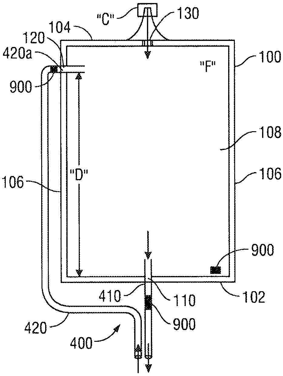
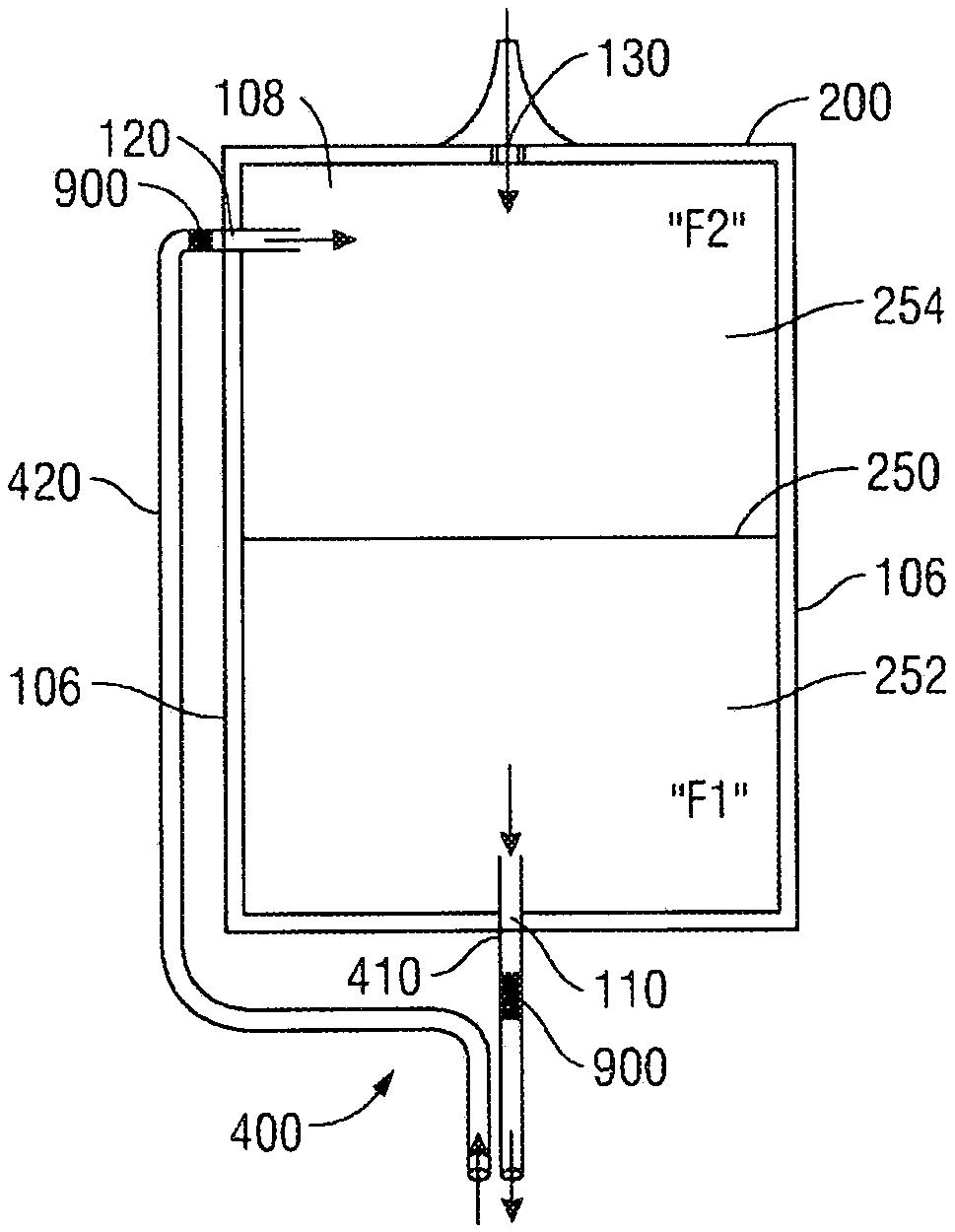
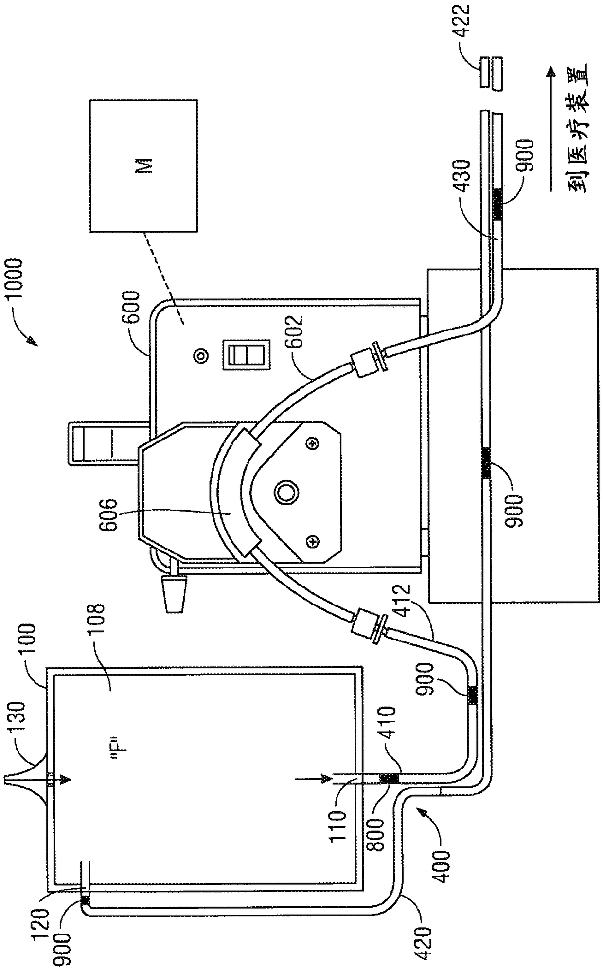
[0026] Typically, bags for containing cooling fluid are provided for implementation into recirculating cooling systems designed to control the temperature of medical devices, such as electrosurgical, cauterization or ablation devices, during use. The bag includes a first port to which a tube is attached to allow cooling fluid to be drawn from the bag and into the system. A second port is formed on the sidewall of the bag and is located near the top portion of the bag. Another tube is connected to the bag through the second port and returns used cooling fluid (eg, cooling fluid that has been circulated through the medical device) back into the bag. The returning cooling fluid may have a higher temperature than the cooling fluid already contained in the bag. The distance between the first port and the second port is used to dissipate heat from the higher temperature cooling fluid returning to the bag before it is drawn from the first port and reintroduced into the system.

[0...


PUM


Abstract

A kit for use with a recirculating cooling system includes a bag. The bag includes a first wall, a second wall opposite the first wall, and a side wall which define a reservoir configured to retain afluid therein. A first port is defined through the first wall and a second port is defined through the side wall or the second wall. The bag is configured to maximize a temperature differential between a fluid proximate the first port and a fluid proximate the second port. Further, the bag is collapsible.

Description

technical field [0001] The present disclosure relates to the use of energy delivery devices. More particularly, the present disclosure relates to a bag configured for use with a system for cooling an energy delivery device. Background technique [0002] Various medical conditions can be treated by delivering energy. For example, procedures such as tissue ablation utilize energy delivery devices (eg, ablation needles, ablation probes, ablation catheters, etc.) to remove unhealthy tissue, including cancer cells, from a patient. Energy delivery devices may operate by direct discharge, electromagnetic energy, microwave energy, or other types of energy. Energy is typically passed through one or more electrodes, causing tissue in contact with it to be heated to ablation temperatures. [0003] During use, the energy delivery device may require cooling to maintain a safe operating temperature and avoid damage to the energy delivery device and / or surrounding tissue. In some cases...

Claims


Application Information

Patent Timeline
Patent Type & Authority Applications(China)
IPC IPC(8): A61B18/00A61B18/12A61B90/00
CPCA61B18/1492F04B23/02F28D20/0039F28D2020/0069A61B18/00A61B2018/00023A61B2018/00577F04B43/08F04B43/12F28D2021/005A61B18/1815F28D15/00F28F27/00F28F2250/08
Inventor W·J·迪克汉斯
Owner COVIDIEN LP
Features
  • R&D
  • Intellectual Property
  • Life Sciences
  • Materials
  • Tech Scout
  • Unparalleled Data Quality
  • Higher Quality Content
  • 60% Fewer Hallucinations
Learn More