Check patentability & draft patents in minutes with Patsnap Eureka AI!

Optical fiber protection structure and manufacturing method of optical element

A technology for optical fiber protection and structure, which is applied in the field of optical fiber protection structure and optical element manufacturing, and can solve the problems of deterioration of optical properties of optical fiber, difficult to use curing shrinkage, etc.

Active Publication Date: 2020-10-23
FUJIKURA LTD
View PDF15 Cites 0 Cited by
  • Summary
  • Abstract
  • Description
  • Claims
  • Application Information

AI Technical Summary

Problems solved by technology

However, there are currently few materials that have both physical properties of low cure shrinkage and low refractive index. Therefore, in order to prevent the light guided by the optical fibers 611 and 612 from leaking in the structure 600, the resin is made of a low refractive index material. For 640A and 640B, it is difficult to use materials with low cure shrinkage
In other words, in the optical combination structure 600, it is difficult to solve both the problems of the generation of micro-vents and the prevention of light leakage. From this point, the problem of deterioration of the optical characteristics of the optical fiber also occurs.

Method used


Image

  • Optical fiber protection structure and manufacturing method of optical element
  • Optical fiber protection structure and manufacturing method of optical element
  • Optical fiber protection structure and manufacturing method of optical element

Examples


Embodiment Construction

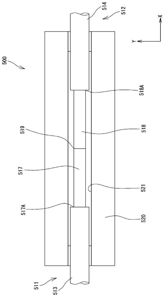
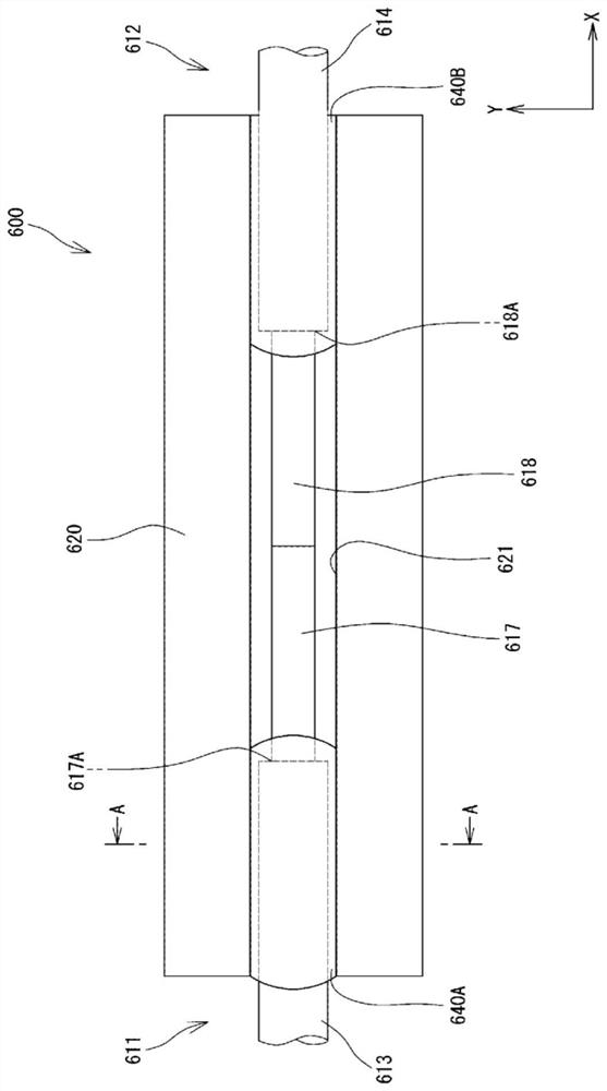
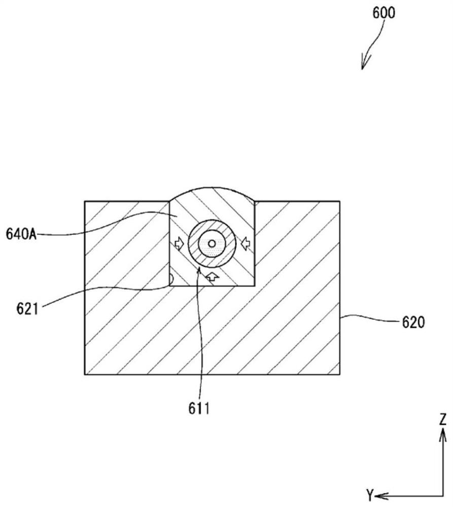
[0050] Below, refer to Figure 5 ~ Figure 20B Embodiments of the optical fiber protection structure and the optical combination structure using the optical fiber protection structure of the present invention will be described in detail. exist Figure 5 ~ Figure 20B In , the same reference numerals are attached to the same or corresponding constituent elements, and repeated explanations are omitted. In addition, in Figure 5 ~ Figure 20B In some cases, the scale and size of each constituent element may be exaggerated, and some constituent elements may be omitted.

[0051] Figure 5 It is a plan view showing the light combining path structure 1 in the first embodiment of the present invention, Figure 6 yes Figure 5 The BB line section view. Such as Figure 5 as well as Figure 6 As shown, the optical combiner structure 1 includes: an optical combiner 10 , which includes mutually fused optical fibers 11 , 12 ; and a fiber housing portion 20 , which protects the fused po...


PUM


Abstract

The present invention provides an optical fiber protection structure capable of reducing deterioration of optical properties of an optical fiber in a high-temperature environment, and a method of manufacturing an optical element using the optical fiber protection structure. The optical combination path structure (1) protects the element exposed part (17, 18) where the element (15, 16) is exposed from the coating (13, 14) of the optical fiber. The optical combined path structure (1) has: a fiber receiving part (20), which is formed with a fiber receiving groove (21), and the fiber receiving groove (21) accommodates the element wire exposed parts (17, 18) inside; the fixing resin (40A , 40B), which is filled in the fiber storage tank (21), and a part of the coating (13, 14) is fixed in the fiber storage tank (21); The ends of (17, 18) seal between the plain wires (15, 16) and the coating (13, 14). The sealing resin (42A, 42B) is formed to be separated from the inner surface of the fiber storage tank (21).

Description

technical field [0001] The present invention relates to an optical fiber protection structure and a method of manufacturing an optical element, and more particularly to an optical fiber protection structure in which at least a part of an optical fiber is accommodated, and an optical combination structure using the optical fiber protection structure. Background technique [0002] For example, when connecting optical fibers, it is often necessary to remove the coating of the optical fiber and fuse the plain wires of the optical fiber to connect. , may break. In order to prevent such a problem, for example, the optical fiber protection structure disclosed in Patent Document 1 may be applied. figure 1 It is a plan view showing an optical combination structure 500 to which such a conventional optical fiber protection structure is applied. Such as figure 1 As shown, according to the optical combined path structure 500, the fused portion 519 of the optical fibers 511, 512 and th...

Claims


Application Information

Patent Timeline
Patent Type & Authority Patents(China)
IPC IPC(8): G02B6/255
CPCG02B6/255G02B6/2558G02B6/3636G02B6/3652
Inventor 中里弘人藤田智之石田和也
Owner FUJIKURA LTD
Features
  • R&D
  • Intellectual Property
  • Life Sciences
  • Materials
  • Tech Scout
  • Unparalleled Data Quality
  • Higher Quality Content
  • 60% Fewer Hallucinations
Learn More