
Steel pipe cutting device

A technology for cutting devices and steel pipes, applied in the direction of pipe shearing devices, shearing devices, and accessories of shearing machines, etc., can solve problems such as low efficiency and troublesome operation, and achieve the effects of convenient operation, simple structure, and improved cutting efficiency

Inactive Publication Date: 2019-01-01
温州市宇田钢管有限公司
View PDF6 Cites 5 Cited by
  • Summary
  • Abstract
  • Description
  • Claims
  • Application Information

AI Technical Summary

Problems solved by technology

Steel pipes often need to be cut before use. Traditional cutting devices are inefficient and cumbersome to use.

Method used


Image

  • Steel pipe cutting device
  • Steel pipe cutting device
  • Steel pipe cutting device

Examples


Embodiment Construction

[0017] The following will clearly and completely describe the technical solutions in the embodiments of the present invention with reference to the accompanying drawings in the embodiments of the present invention. Obviously, the described embodiments are only some, not all, embodiments of the present invention.

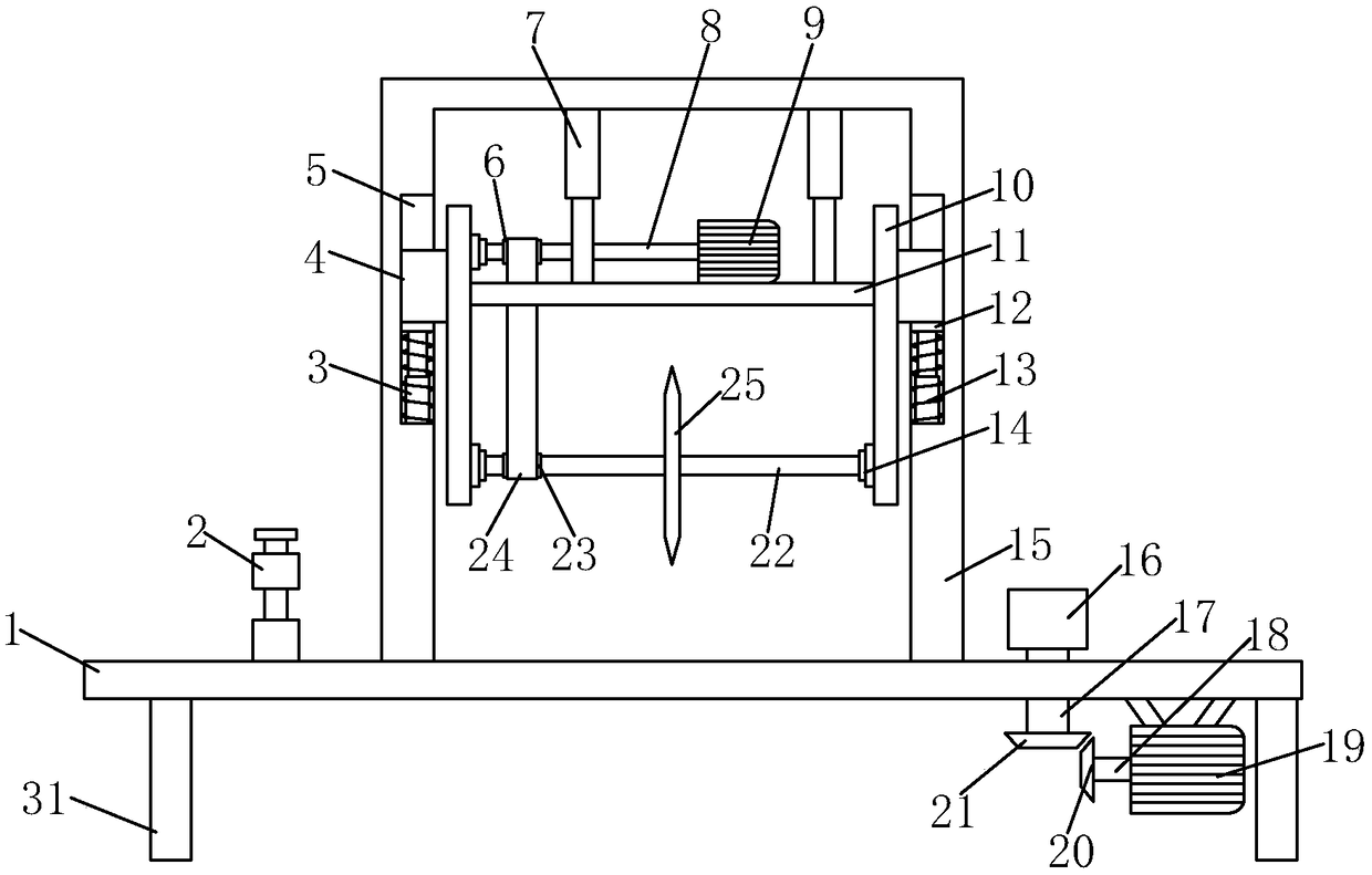
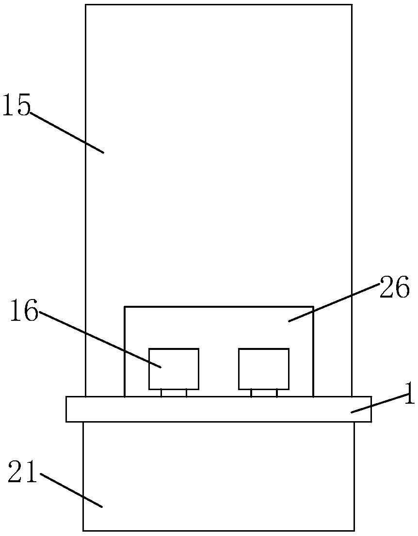
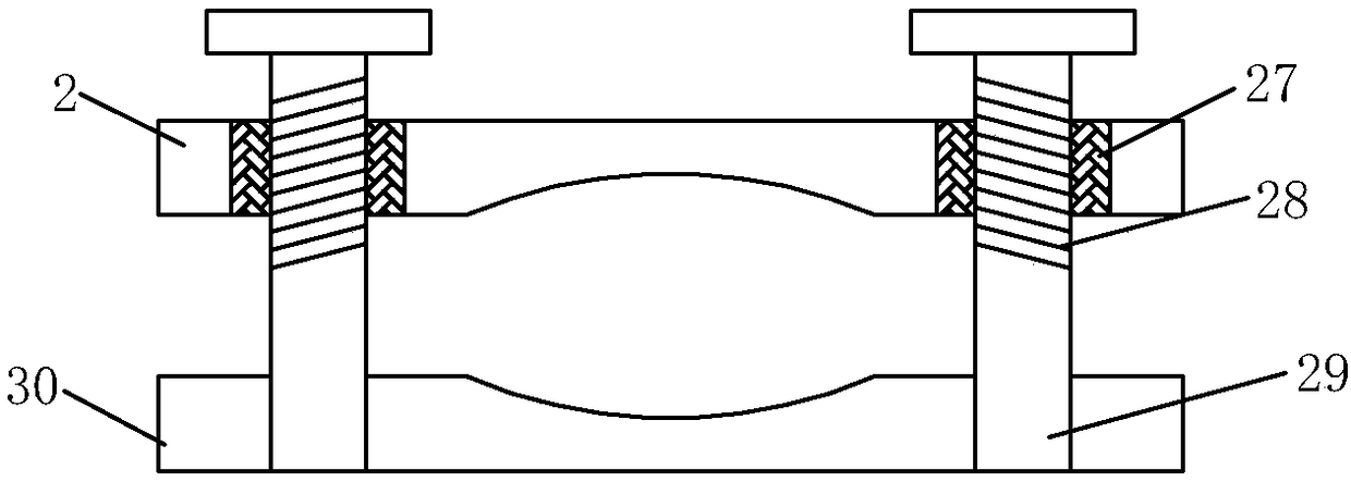
[0018] refer to Figure 1-3 , a steel pipe cutting device, including a base 1, the material of the base 1 is hard alloy steel, the strength is extremely high and the stress resistance is excellent, and it can bear heavy steel pipes, and the lower end of the base 1 is fixedly installed on both sides with support plates 31 A second AC asynchronous motor 19 is fixedly installed on one side of the lower end of the base 1 between the support plates 31, the model of the second AC asynchronous motor 19 is a YEJ-100L three-phase asynchronous motor, and the second AC asynchronous motor 19 is provided with a power control switch , and the second AC asynchronous motor 19 is ele...


PUM


Abstract

The invention relates to the technical field of steel pipe cutting, in particular to a steel pipe cutting device. The device comprises a base. Supporting plates are fixedly mounted on the two sides ofthe lower end of the base correspondingly. A second alternating current asynchronous motor is fixedly mounted on one side of the lower end of the portion, between the supporting plates, of the base.An output shaft of the second alternating current asynchronous motor is fixedly connected with a second driving rotary shaft. A second driven rotary shaft is arranged on the second driving rotary shaft through a first transmission structure, penetrates through the base and stretches to the upper end of the base. A guide wheel is fixedly mounted on the portion, located at the upper end of the base,of the second driven rotary shaft. A cutting frame is fixedly mounted in the position, adjacent to the guide wheel, of the base. Moving plates are arranged in the cutting frame through sliding structures correspondingly. According to the steel pipe cutting device, the second alternating current asynchronous motor is utilized firstly for driving the guide wheel to achieve a guide effect on a to-be-cut steel pipe, the cutting efficiency can be greatly improved, meanwhile, electric telescopic rods drive a fixing plate to move up and down, and it can be guaranteed that a cutting disc starts and stops cutting the steel pipe.

Description

technical field [0001] The invention relates to the technical field of steel pipe cutting, in particular to a steel pipe cutting device. Background technique [0002] Steel pipes have a hollow section whose length is much greater than the diameter or circumference of steel. According to the cross-sectional shape, it can be divided into circular, square, rectangular and special-shaped steel pipes; according to the material, it can be divided into carbon structural steel pipes, low alloy structural steel pipes, alloy steel pipes and composite steel pipes; Steel pipes for thermal equipment, petrochemical industry, machinery manufacturing, geological drilling, high-pressure equipment, etc. are divided into seamless steel pipes and welded steel pipes according to the production process, among which seamless steel pipes are divided into hot-rolled and cold-rolled. Welded steel pipes are divided into straight seam welded steel pipes and spiral seam welded steel pipes. The steel p...

Claims


Application Information

Patent Timeline
Patent Type & Authority Applications(China)
IPC IPC(8): B23D33/02B23D21/00
Inventor 谢军项文达章竞州
Owner 温州市宇田钢管有限公司
Learn More