Wind tunnel vehicle model and manufacturing method thereof
A manufacturing method and model technology, applied in the field of wind tunnel car model and its manufacturing, can solve the problems of large cost and long cycle, and achieve the effect of reducing cost, reducing demand, and shortening the change process cycle.
- Summary
- Abstract
- Description
- Claims
- Application Information
AI Technical Summary
Problems solved by technology
Method used
Image

Examples
Embodiment Construction
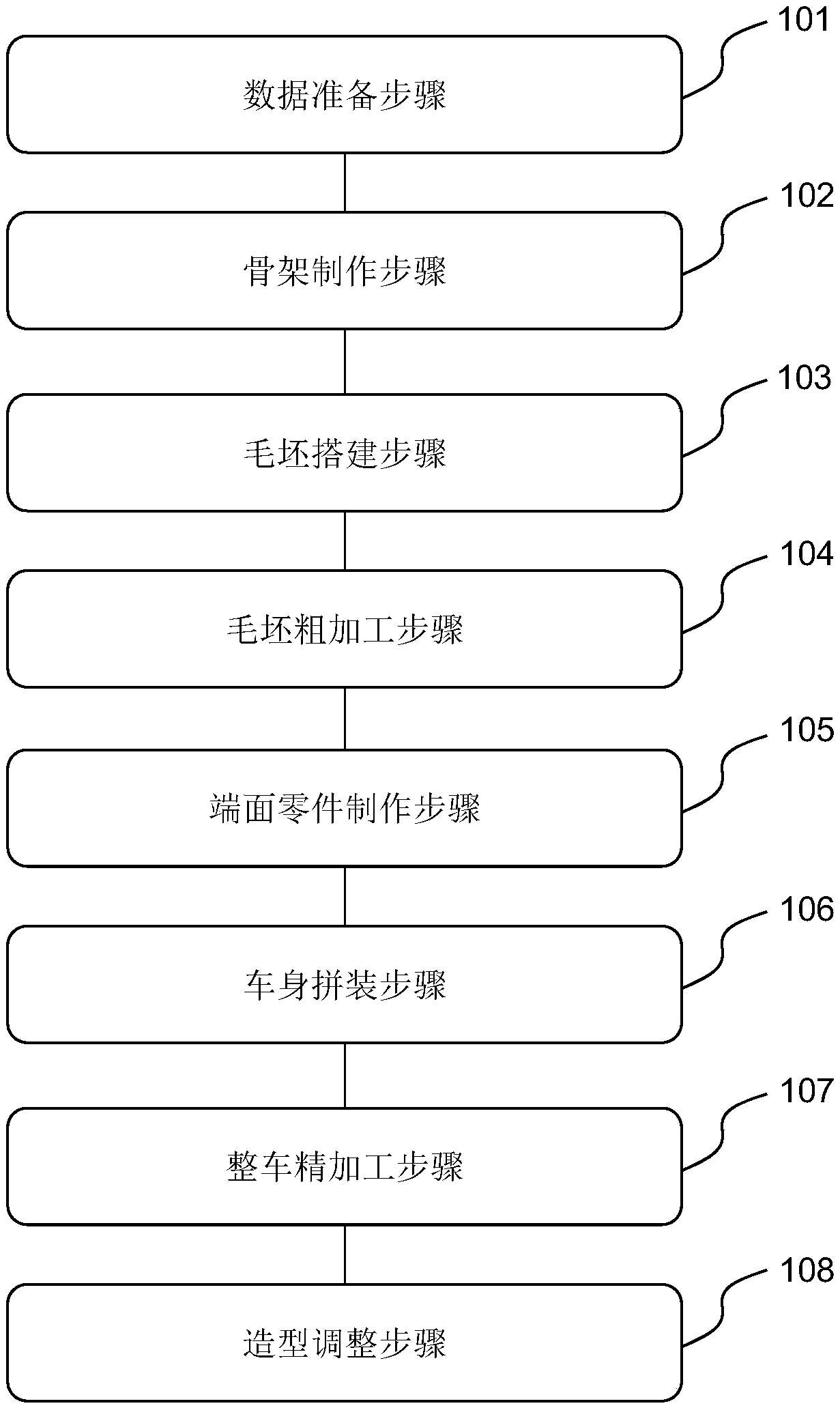
[0035] refer to figure 1 as shown, figure 1 A flowchart of a method for manufacturing a wind tunnel car model according to an embodiment of the present invention is disclosed. The manufacturing method of this wind tunnel car model comprises the steps:
[0036]101. Data preparation step. According to the chassis data and appearance modeling data, the outer modeling data surface is determined, and the outer modeling data surface is used as the reference, and the data surface of the skeleton installation, the end surface parts installation data surface and the rough machining data surface are determined by offsetting inward respectively. The wind tunnel car model of the present invention is a 1:1 model, and the chassis generally adopts a batch body chassis, and the appearance of the body has original design data. According to the chassis data and the exterior modeling data, the exterior modeling data surface of the vehicle body can be determined. On the basis of the external ...
PUM
 Abstract
Description
Claims
Application Information
 - Generate Ideas
- Intellectual Property
- Life Sciences
- Materials
- Tech Scout
- Unparalleled Data Quality
- Higher Quality Content
- 60% Fewer Hallucinations
Browse by: Latest US Patents, China's latest patents, Technical Efficacy Thesaurus, Application Domain, Technology Topic, Popular Technical Reports.
© 2025 PatSnap. All rights reserved.Legal|Privacy policy|Modern Slavery Act Transparency Statement|Sitemap|About US| Contact US: help@patsnap.com