Spatial polarization filter

A polarized filter and polarized wave technology, applied in the microwave field, can solve the problems of inability to apply, unfavorable full-polarization stealth, etc., and achieve the effects of simple structure, simple processing and good performance

Inactive Publication Date: 2019-01-08
AIR FORCE UNIV PLA
View PDF10 Cites 2 Cited by
  • Summary
  • Abstract
  • Description
  • Claims
  • Application Information

AI Technical Summary

Problems solved by technology

[0006] In addition, traditional spatially polarized filters often have better single-polarization passband characteristics in their bands, but maintain high mirror reflections for cross-polarization modes polarized in the passband, forming a larger Back to RCS, it is not conducive to full polarization stealth, so it cannot be applied to modern weapons and equipment

Method used


Image

  • Spatial polarization filter
  • Spatial polarization filter
  • Spatial polarization filter

Examples


Embodiment Construction

[0017] The technical solution of the present invention will be described in further detail below in conjunction with the accompanying drawings and specific embodiments.

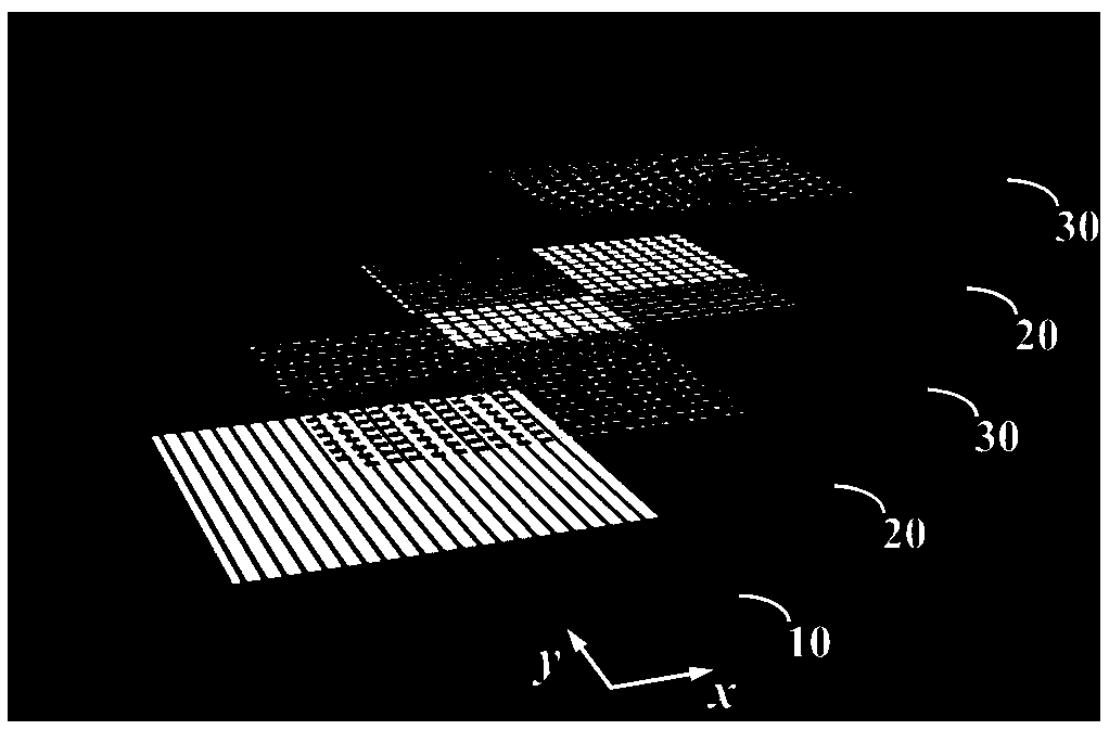
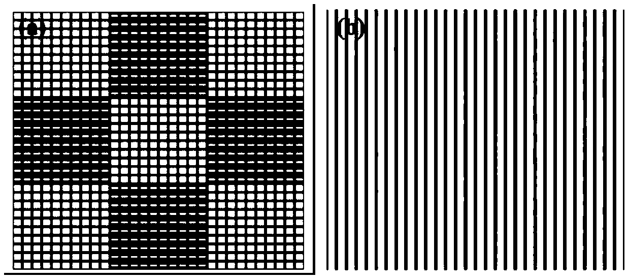
[0018] Such as figure 1 As shown, the designed spatial polarization filter is composed of three layers of metal and two layers of dielectric. The thickness of the metal layer is 0.036mm, and the thickness of the dielectric layer is 1mm. In addition, the schematic diagram is to clearly show the structure of the polarization filter. There are virtually no gaps between the five layers. Among them, structure 10 is the first metal layer, and the specific structure is a polarized grid with a grid width of 3.5mm, a grid spacing of 5mm, and a grid thickness of 0.036mm; structure 20 is an intermediate dielectric layer, which is printed by ordinary Composed of circuit boards, the dielectric constant range is 2.2-10, and the magnetic permeability is 1. The intermediate dielectric layer of the structure 20 can also be ...


PUM


Abstract

The invention discloses a spatial polarization filter, which is composed of three metal layers and two dielectric layers. The first metal layer in the three metal layers is a periodically arranged metal grid bar structure. The first metal layer can totally reflect y-polarized wave while maintaining high transparency to x-polarized wave. The second and third metal layers are metal layers with diffuse scattering surface distributed by two kinds of metal patches according to checkerboard pattern, which can diffuse the y-polarized wave reflected by the first metal layer. Both layers of dielectricare made up of ordinary printed circuit boards. The spatial polarization filter provided by the invention can not only realize the effect of polarization filtering in a wide band, but also diffuse they-polarized reflected wave in the Ku band so as to greatly reduce the backward RCS. At the same time, the spatial polarization filter has the characteristics of simple fabrication, high efficiency and multi-function.

Description

technical field [0001] The invention belongs to the field of microwave technology, and in particular relates to a spatial polarization filter design. Background technique [0002] Radar cross section (Radar cross section, RCS) has an extremely important position in the field of radar detection, and its size is directly related to the range of radar detection. In modern warfare, in order to improve the combat capability of aircraft, countries all over the world are sparing no effort to develop RCS reduction technology to reduce the probability of aircraft being detected by radar and improve the survivability of aircraft. In the prior art, the main ways of using metamaterials to reduce RCS include electromagnetic absorber and diffuse scattering technology. The electromagnetic absorber mainly converts the irradiated electromagnetic energy into internal energy and dissipates it, so as to achieve the purpose of reducing the back-to-back RCS. The diffuse scattering technology ma...

Claims


Application Information

Patent Timeline
IPC IPC(8): H01Q15/24
CPCH01Q15/24
Inventor 郭文龙王光明高向军刘凯越蔡通
Owner AIR FORCE UNIV PLA
Why Eureka
Try Eureka