Supercharge Your Innovation With Domain-Expert AI Agents!

Locking release and power supply device of a wire-suspended gyro north finder

A technology of a power supply device and a gyroscope, applied in the direction of a rotating gyroscope, etc., can solve the problems of the stress state and shape change of the suspension belt, the long locking and loosening action time, and the poor contact of the bypass contact, so as to reduce the magnetic interference. source, reduce overall weight, solve the effect of synergy problem

Active Publication Date: 2021-12-31
TIANJIN NAVIGATION INSTR RES INST
View PDF7 Cites 0 Cited by
  • Summary
  • Abstract
  • Description
  • Claims
  • Application Information

AI Technical Summary

Problems solved by technology

[0003] The locking and loosening of the existing wire-suspended gyro north-seekers mostly adopt the axial lifting and lowering type, which not only takes a long time to lock and loosen the action, but also has a large related structure size, and more importantly, the lifting action of the gyroscope is easy to cause The suspension belt is in a bent state, resulting in obvious changes in the stress state and shape of the suspension belt, which makes the zero stability of the system worse
[0004] The bypass power supply of the existing gyroscope in the locked state mostly adopts the method of separating the locking and releasing mechanism from the bypass power supply device, which has a complex structure and a large volume, and the two sets of mechanisms need to be adjusted in coordination, making assembly and debugging difficult and easy. The phenomenon that the lock-off mechanism is locked in place and the bypass contact is not in good contact, etc.

Method used


Image

  • Locking release and power supply device of a wire-suspended gyro north finder
  • Locking release and power supply device of a wire-suspended gyro north finder
  • Locking release and power supply device of a wire-suspended gyro north finder

Examples


Embodiment Construction

[0026] The embodiments of the present invention will be described in detail below in conjunction with the accompanying drawings. It should be noted that the embodiments are illustrative, not restrictive, and cannot limit the protection scope of the present invention.

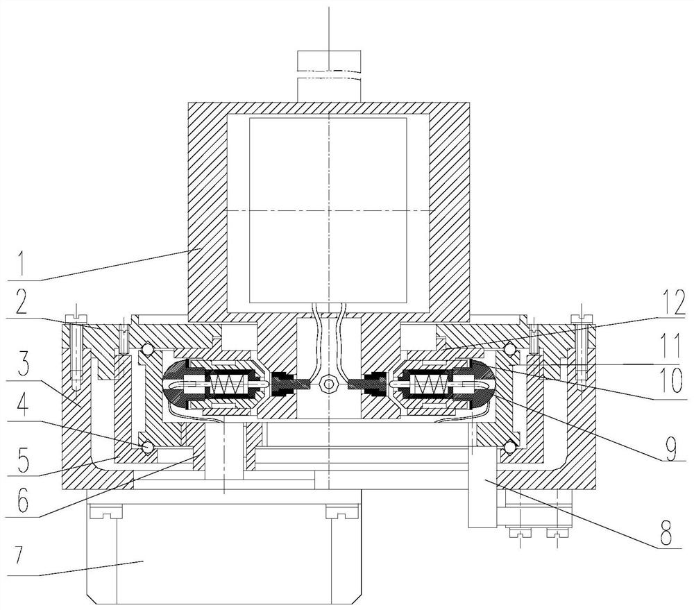
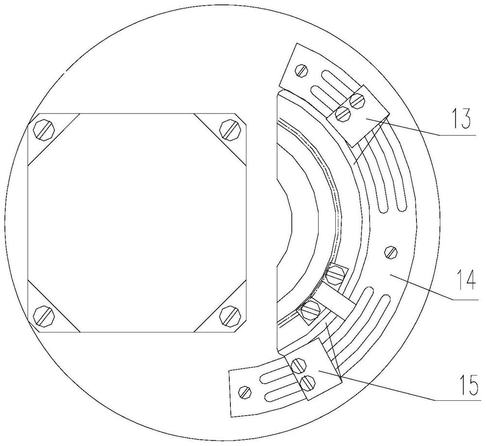
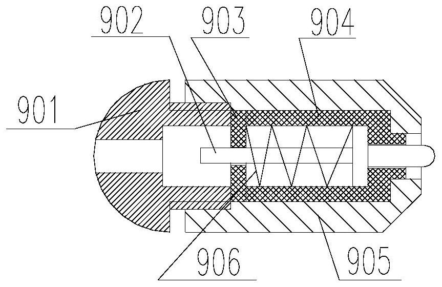
[0027] A locking, releasing and power supply device for a wire-suspended gyro north finder, comprising a gyroscope (1), a base (2), a motor mounting frame (3), a ball (4), a ball press seat (5), Pinion (6), drive motor (7), lock release stopper (8), ejector pin assembly (9), shrapnel (10), lock release cam (11), ejector pin seat (12), lock sensor ( 13), sensor adjustment guide rail (14) and loose sensor (15). The gyroscope is a locked and loose part, a sensitive part with a built-in high-speed rotating motor and suspended from a frame system by a metal wire.

[0028] The locking release and power supply device is arranged on the lower periphery of the gyroscope, the base (2) is fixedly installed below the gyros...


PUM


Abstract

The invention relates to a locking and releasing device and a power supply device of a wire-suspended gyro north finder. The locking and releasing device and the power supply device are arranged on the outer periphery of the lower part of the gyroscope, and several evenly distributed ejector pin assemblies are used to radially hold the gyroscope. ;The ejector pin assembly is driven by a transmission chain consisting of a driving motor, a pinion and a lock-off cam. The lock-off cam is supported by a ball located in a "◇"-shaped track; the lock-off cam is equipped with a lock-off stopper, which is installed on the motor The sensor on the frame adjusts the guide rail, the locking sensor and the loosening sensor to form a position detection device. The invention has a compact design structure, reduces the size and weight of the system, and effectively avoids the change of the shape of the gyroscope suspension belt caused by the traditional axial lifting type locking and loosening. The bypass power supply device of the gyroscope is integrated inside the ejector pin assembly, and the locking and power supply functions of the gyroscope are completed by the same mechanism, which simplifies the structural design and effectively solves the problem of synergy between the two devices of locking and releasing and bypass power supply , improving the reliability of the system.

Description

technical field [0001] The invention relates to the technical field of inertial navigation equipment, in particular to a locking and releasing device and a power supply device for a wire-suspended gyro north finder. Background technique [0002] The suspension wire gyro north finder is a kind of orientation equipment. Its working principle is: use an elastic metal wire to hang a gyroscope sensitive part (hereinafter referred to as gyroscope) with a high-speed rotating gyroscope motor inside. The external torque generated by the hairspring etc. is balanced, and the gyroscope reciprocates and precesses around the meridian plane. The angle of precession is measured by an optical or photoelectric sensor, and the true north direction is calculated. The gyroscope is suspended from the frame by wires. When orienting, firstly the gyroscope is locked. When starting the gyroscope, power is supplied to the gyroscope through the bypass contact and the conductive hairspring at the same...

Claims


Application Information

Patent Timeline
Patent Type & Authority Patents(China)
IPC IPC(8): G01C19/26G01C19/04
CPCG01C19/04G01C19/26
Inventor 程志伟张若玉丁凤薛琳生王亦璐付伟王欣
Owner TIANJIN NAVIGATION INSTR RES INST
Features
  • R&D
  • Intellectual Property
  • Life Sciences
  • Materials
  • Tech Scout
  • Unparalleled Data Quality
  • Higher Quality Content
  • 60% Fewer Hallucinations
Learn More