
Drain valve for flush tank and flush tank with drain valve
A technique for drain valves and flush tanks, applied in the field of sanitary flush tanks, which can solve problems such as difficulty in dismantling drain valves, and achieve the effect of improving and simplifying operations
- Summary
- Abstract
- Description
- Claims
- Application Information
AI Technical Summary
Problems solved by technology
Method used
Image

Examples
Embodiment Construction
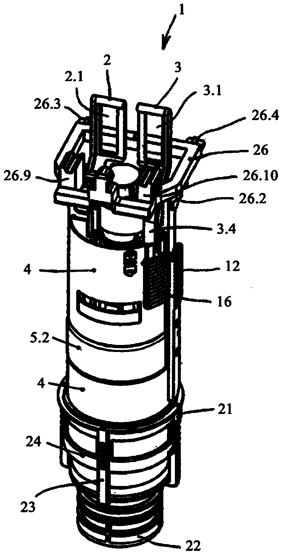
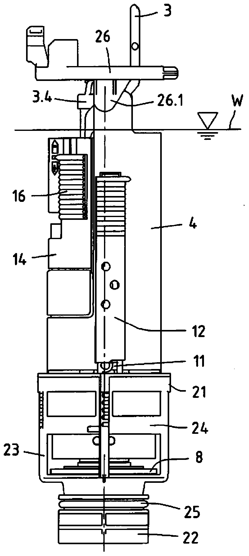
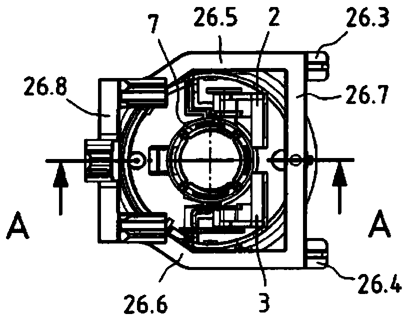
[0026] The figures of the figures show a drain valve 1 which can be installed in a sanitary cistern, in particular in a concealed cistern. The drain valve 1 is preferably designed as a dual-displacement drain valve, ie a larger flush volume for so-called full flushes or a smaller flush water volume for so-called partial flushes can be selectively delivered by means of the drain valve. For operating the drain valve 1 , an operating device (not shown) is arranged in the upper region of the tank. The operating device has two operating elements that can be controlled independently of one another. By way of example, the operating elements are implemented as movably mounted pushbuttons, wherein each pushbutton is assigned a lifting mechanism (not shown). The respective lifting mechanism is coupled to one of the two pull tabs 2, 3 of the drain valve 1, which has at its upper end an elongated lug 2.1, 3.1 in which the lifting mechanism engages.
[0027] The drain valve 1 has a subst...
PUM
 Abstract
Description
Claims
Application Information