Automatically-processing production system and process for seat board of chair

A production system and seat board technology, applied to wood processing equipment, manufacturing tools, special forming/shaping machines, etc., can solve the problems of low production efficiency, single practicability, high production cost, etc., and achieve high trimming quality and improved High work efficiency and high degree of automation

Inactive Publication Date: 2019-01-15
ANJI QIANGHONG FURNITURE CO LTD
1 Cites 1 Cited by

AI-Extracted Technical Summary

Problems solved by technology

[0005] Aiming at the deficiencies of the prior art, the present invention provides an automatic processing and production system for chair seat boards. A feeding mechanism, a preprocessing mechanism, a cutting mechanism and a feeding mechanism are arranged around the circumference, and then the feeding mechanism is realized through the continuous rotation of several feeding me...

Method used

In the present embodiment, by arranging drive mechanism 1 to drive feeding mechanism 2 rotations, feeding mechanism 2 is rotated to feeding mechanism 3, pretreatment mechanism 4, cutting mechanism 5 and blanking mechanism 6 stations successively, completes wood The integrated work of block feeding, sorting, trimming and unloading has high trimming quality and a high degree of automation, which improves production efficiency, reduces production costs, and saves labor output.
In the present embodiment, by arranging the rack c61, when the feeding mechanism 2 enters the station, the gear 231 on the rotating shaft 23 is engaged with the rack c61, so that the rotating shaft 23 rotates, and the supporting plate 24 moves along Turn clockwise, and one end of the baffle plate c243 gradually goes downward. Since the baffle plate 26 is provided with a roller 263, the friction force between the block and the extruding plate 26 is reduced, so that the block slides downward due to gravity and falls on the receiving plate. In the trough 63, when the feeding mechanism 2 rotates to the rack d62, the gear 231 meshes with the rack d62, the supporting plate 24 rotates counterclockwise, returns to the initial state, and moves to the feeding mechanism 3, which realizes the automatic removal of the wooden blocks. Unloading improves production efficiency and saves labor output.
In the present embodiment, by being fixedly arranged on the sliding shaft 22 by the limiting block d81, and by setting the slide rail 82, the feeding mechanism 2 is supported while the feeding mechanism 2 is limited, which improves the overall stability.
In the present embodiment, by setting the distance between the cutting pieces 53 as L1, the distance between the slits 244 as L2, the relationship between the two is L1=L2, so that the feeding mechanism 2 enters During this station, the cutting mechanism 5 can enter the cutting groove 244 to trim the wood block. Its structure is ingenious, which ensures the trimming quality of the wood block and saves labor output.
In the present embodiment, by setting the rack a41, after the feeding mechanism 2 enters the station, the gear 231 on the rotating shaft 23 is engaged with the ...

Abstract

The invention relates to an automatically-processing production system and process for the seat board of a chair. The automatically-processing production system comprises: a driving mechanism, which comprises a frame, rotating shafts and a driving member; material conveying mechanisms, which are fixedly arranged on the rotating shafts, wherein the number of the material conveying mechanisms is plural, the material conveying mechanisms are arrayed along the axes of the rotating shaft at an equal interval, the periphery of the frame is circumferentially provided with a feeding mechanism, a pre-processing mechanism, a cutting mechanism and a blanking mechanism along the centers of the material conveying mechanisms, and the feeding mechanism, the pre-processing mechanism, the cutting mechanismand the blanking mechanism are sequentially arranged along the processing direction of a workpiece; a pushing mechanism, which is located between the feeding mechanism and the cutting mechanism; anda limiting mechanism, which is coaxially arranged under the material conveying mechanisms. The automatically-processing production system and process of the invention solves the technical problems ofsingle purpose, consumption of time and labor, low production efficiency and high production cost in the prior art.

Application Domain

Profiling/shaping machines

Technology Topic

Rotational axis

Image

  • Automatically-processing production system and process for seat board of chair
  • Automatically-processing production system and process for seat board of chair
  • Automatically-processing production system and process for seat board of chair

Examples

  • Experimental program(2)

Example Embodiment

[0086] Example 1
[0087] The following describes in detail the embodiments of the present invention, examples of which are illustrated in the accompanying drawings, wherein the same or similar reference numerals refer to the same or similar elements or elements having the same or similar functions throughout. The embodiments described below with reference to the accompanying drawings are exemplary, and are intended to explain the present invention and should not be construed as limiting the present invention.
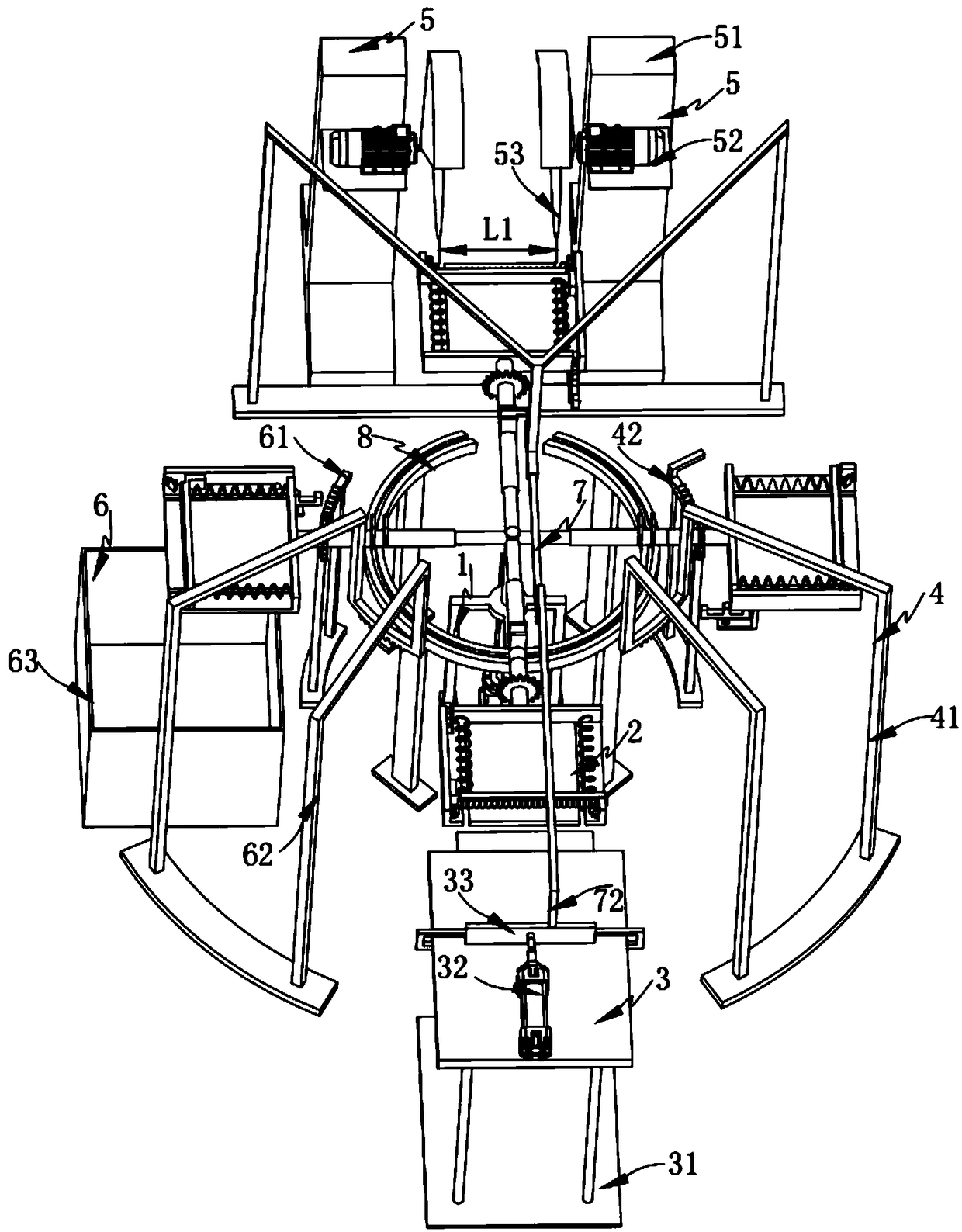
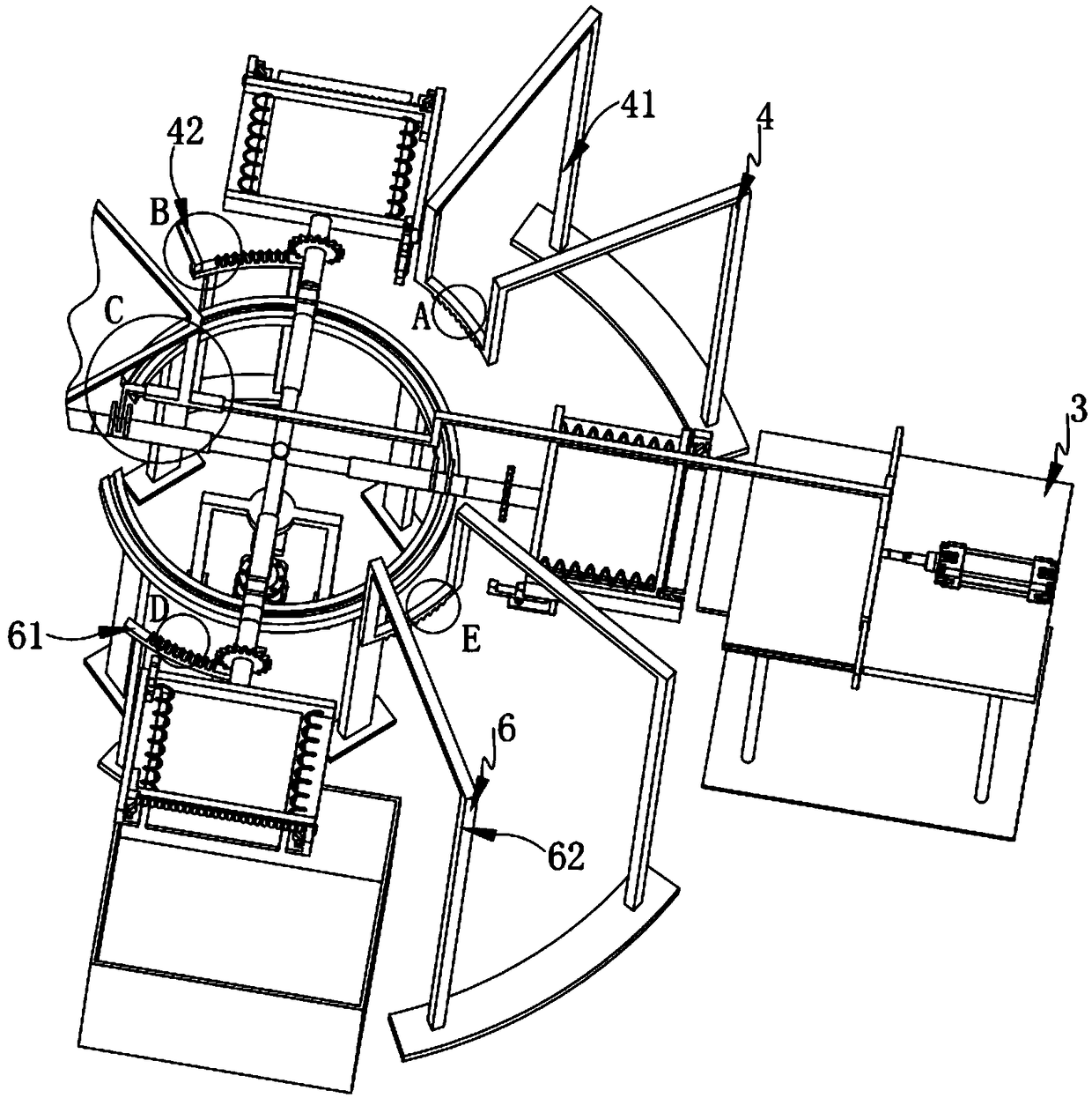
[0088] like figure 1 , Figure 8 , Figure 15 , Figure 16 and 17 As shown, an automatic processing and production system for a chair seat panel includes:
[0089] A driving mechanism 1, the driving mechanism 1 includes a frame 11, a rotating shaft 12 and a driving member 13;
[0090] Feeding mechanism 2, the feeding mechanism 2 is fixedly arranged on the rotating shaft 12, the number of which is several, the feeding mechanism 2 is arranged in an equidistant array along the axis of the rotating shaft 12, and is driven by the driving mechanism 1 Driven to rotate, along the center of the feeding mechanism 2, a feeding mechanism 3, a pretreatment mechanism 4, a cutting mechanism 5 and a feeding mechanism 6 are arranged on the circumference of the frame 11. The feeding mechanism 3, the pretreatment mechanism The mechanism 4, the cutting mechanism 5 and the blanking mechanism 6 are respectively arranged along the processing sequence direction of the workpiece;
[0091] Pushing mechanism 7, which is located between the feeding mechanism 3 and the cutting mechanism 5, one end of which is connected to the feeding mechanism 3; and
[0092] The limiting mechanism 8 is coaxially arranged below the feeding mechanism 2 .
[0093] In this embodiment, by setting the drive mechanism 1 to drive the feeding mechanism 2 to rotate, the feeding mechanism 2 rotates to the stations of the feeding mechanism 3, the pretreatment mechanism 4, the cutting mechanism 5 and the unloading mechanism 6 in turn, so as to complete the loading of the wood block. The integrated work of feeding, finishing, trimming and blanking has high trimming quality and high degree of automation, which improves production efficiency, reduces production costs and saves labor output.
[0094] It should be noted here that the driving member 13 is a driving member that can realize a rotating function, and a motor is preferably used in the present invention.
[0095] further, as Figure 8 , Figure 9 , Figure 10 and Figure 11 As shown, the feeding mechanism 2 includes:
[0096] a connecting shaft 21, one end of the connecting shaft 21 is connected and arranged on the rotating shaft 12, and the other end of the connecting shaft 21 is arranged in a rectangular shape;
[0097] Sliding shaft 22, the center of the sliding shaft 22 is provided with a rectangular groove, which is arranged in cooperation with the other end of the connecting shaft 21, and one end of which is slidably arranged on the connecting shaft 21, and the sliding shaft 22 is provided with a stopper plate 221, two baffle plates 221 are provided, and a push groove 222 is formed between the two baffle plates 221;
[0098] a rotating shaft 23, the rotating shaft 23 and the other end of the sliding shaft 22 are arranged to rotate coaxially, and the rotating shaft 23 is provided with a gear 231;
[0099] The support plate 24, the length direction of the support plate 24 is provided with a baffle a241, the width direction is provided with a baffle b242 and a baffle c243, the baffle a241 is fixed on the other end of the rotating shaft 23 , and the support plate 24 is provided with a cut slot 244 and a limit opening 245, the cut slot 244 is symmetrically arranged along the center line of the length direction of the support plate 24, and the limit opening 245 is provided through the One end of the baffle a241;
[0100] Spring a25, the spring a25 is symmetrically arranged along the center line of the length direction of the material support plate 24, and one end of the spring a25 is fixedly arranged on the baffle plate a241;
[0101]The pressing plate 26 is slidably arranged on the holding plate 24, and is fixedly arranged on the other end of the spring a25, and a notch 261 and a pressing block 262 are arranged on one side thereof. The pressing block 262 is arranged in cooperation with the limit opening 245, and the pressing plate 26 is provided with a roller 263, and the roller 263 is rotatably arranged on the pressing plate 26, and the number of the rollers is several;
[0102] The wooden block stopper 27 is symmetrically arranged on the baffle b242 and the baffle c243 along the center line in the longitudinal direction of the pallet 24 , and includes a stopper 271 , a spring b272 and a limit block a273, the block 271 is fixedly arranged at the end of the support plate 24, the spring b272 is arranged on one side of the stop block 271, and is angled to the stop block 271 set, the limit block a273 is set on the spring b272; and
[0103] The squeeze plate limiter 28 is arranged below the material support plate 24 and includes a mounting plate 281, a support block 282 and a limit block b283, and the mounting plate 281 is fixedly arranged on the On the lower surface of the support plate 24, the support block 282 is slidably arranged on the mounting plate 281 by a spring, and the support block 282 is set in a "mountain" shape, and the middle top is set as a spherical shape, and the limit block The b283 is connected to the support block 282 through a spring, and is slidably disposed in the limiting opening 245 , and the top of the limiting block b283 is spherical.
[0104] In this embodiment, by setting the rectangular fit between the connecting shaft 21 and the sliding shaft 22, the sliding shaft 22 can slide on the connecting shaft 21 while rotating with the connecting shaft 21, and the connecting shaft 21 is driven by the driving member 13 to rotate. By being arranged at the end of the spring a25, the squeeze plate 26 is set, so that when the wooden block enters the support plate 24, due to the elasticity of the spring a25, the squeeze plate 26 is continuously slid to the baffle plate a241, and during the sliding process, The limit block b283 is slid on the mounting plate 281 by the spring, so that the pressure block 262 squeezes the limit block b283 to the bottom until the pressure block 262 moves to the bottom, and the limit block b283 pops out, blocking the pressing plate 26, There is a certain gap between the pressing plate 26 and the wooden block, the structure is ingenious, the position limit is convenient, and the work efficiency is improved; The flexibility of b272 enables the limit block a273 to be pushed open, and the block 271 is provided to block the wood block. The structure is ingenious and the limit is convenient, which avoids the falling of the wood due to shaking and improves the work efficiency. , reducing production costs.
[0105] further, as figure 1 and Figure 14 As shown, the feeding mechanism 3 includes:
[0106] a support table 31, the support table 31 is located on the outer side of the feeding mechanism 2, and is provided with a sliding groove 311;
[0107] a cylinder 32, the cylinder 32 is fixedly arranged on the top of the support table 31;
[0108] a push plate 33, the central position of the push plate 33 is connected with the push shaft of the air cylinder 32; and
[0109] The elastic plate 34 is slidably arranged with the sliding groove 311 , and a spring c341 is provided at one end thereof. The elastic plate 34 is connected to the push plate 33 through a connecting rod 342 .
[0110] In this embodiment, by setting the air cylinder 32 to push the push plate 33, the wooden blocks arranged in front of the push plate 33 are pushed into the support plate 24. Since the elastic plate 34 is connected to the push plate 33 through the connecting rod 342, the push plate 33 is connected to the push plate 33. 33 At the same time as the action, the elastic plate 34 moves at the same time, and since the elastic plate 34 is provided with a spring c341, when the elastic plate 34 is in contact with the support plate 241, the elastic plate 34 is squeezed to slide due to the elasticity of the spring c341. In the groove 311, the push plate 33 continues to push the wood into the support plate 24, the structure is ingenious, the feeding speed is fast, and the production efficiency is improved.
[0111] It is worth mentioning that, in this embodiment, the elastic plate 34 is slidably arranged in the sliding groove 311, so that after the feeding operation is completed, there is a certain distance between the support table 31 and the material supporting plate 24, which avoids The ingenious structure of the interference when the feeding mechanism 2 rotates ensures the realization of the function.
[0112] further, as figure 2 , image 3 and Figure 4 As shown, the preprocessing mechanism 4 includes:
[0113] Rack a41, the rack a41 is arranged in a circular arc, and is arranged above the feeding mechanism 2 through a bracket, and is arranged in mesh with the gear 231;
[0114] Rack b42, the rack b42 is arranged in a circular arc, which is located on one side of the rack a41, and is close to the cutting mechanism 5, and the rack b42 is arranged under the feeding mechanism 2 through a bracket , and it is arranged in mesh with the gear 231; and
[0115] The limiting block c43 is fixedly arranged on the rack b42 and is provided in intermittent contact with the support block 282 .
[0116] In this embodiment, by setting the rack a41, after the feeding mechanism 2 enters the station, the gear 231 on the rotating shaft 23 meshes with the rack a41, so that the rotating shaft 23 rotates, and the feeding plate 24 rotates clockwise. One end of the baffle c243 is gradually downward, the wooden block is in contact with the baffle b242, and one side of the wooden block is aligned. When the feeding mechanism 2 rotates to the rack b42, the gear 231 meshes with the rack b42, and the support plate 24 rotates counterclockwise. , return to the initial state, which realizes the automatic arrangement and alignment of the wooden blocks, improves the work efficiency, and saves labor output; during the movement of the feeding mechanism 2, the limit block c43 touches the support block 282, so that the support block 282 drives the The limit block b283 moves downward, the pressing plate 26 is released, and the wooden block is pressed. By setting the pressing plate 26 and the stopper 271, the automatic pressing of the wooden block is realized, which avoids the Shaking affects subsequent cutting, improves work efficiency, reduces production costs, and saves labor output.
[0117] further, as figure 1 As shown, the cutting mechanism 5 is symmetrically arranged along the center line in the longitudinal direction of the frame 11, and includes:
[0118] a support base 51, the support base 51 is arranged on the ground;
[0119] a motor 52, the motor 52 is fixedly arranged on the support base 51; and
[0120] The cutting blade 53 is coaxially arranged on the rotating shaft of the motor 52 .
[0121] further, as figure 1 and Figure 8 As shown, the distance between the cutting pieces 53 is L1, the distance between the cutting grooves 244 is L2, and the relationship between the two is L1=L2.
[0122] In this embodiment, by setting the distance between the cutting pieces 53 to be L1, the distance between the cutting grooves 244 to be L2, and the relationship between the two is L1=L2, so that the feeding mechanism 2 enters the station , the cutting mechanism 5 can enter the cutting groove 244 to trim the wood block, and its ingenious structure ensures the quality of the wood block trimming and saves labor output.
[0123] further, as figure 2 , Image 6 and Figure 7 As shown, the blanking mechanism 6 includes:
[0124] A rack c61, the rack c61 is arranged below the feeding mechanism 2 through a bracket, and is arranged in mesh with the gear 231;
[0125] Rack d62, the rack d62 is arranged above the feeding mechanism 2 through a bracket, and it is located on the side of the rack c61, and it is close to the feeding mechanism 3, the rack d62 and the gear 231 meshing settings; and
[0126] A receiving chute 63 is provided below the rack c61.
[0127] In this embodiment, by setting the rack c61, when the feeding mechanism 2 enters the station, the gear 231 on the rotating shaft 23 meshes with the rack c61, so that the rotating shaft 23 rotates, and the feeding plate 24 rotates clockwise. One end of the baffle c243 is gradually downward. Since the baffle 26 is provided with a roller 263, the friction between the wooden block and the pressing plate 26 is reduced, so that the wooden block slides down due to gravity and falls on the receiving chute 63. In the middle, when the feeding mechanism 2 rotates to the rack d62, the gear 231 meshes with the rack d62, the support plate 24 rotates counterclockwise, returns to the initial state, and moves to the feeding mechanism 3, which realizes the automatic unloading of wood blocks, Improve production efficiency and save labor output.
[0128] further, as figure 1 , figure 2 and Figure 5 As shown, the push mechanism 7 includes:
[0129] A sliding sleeve 71, the sliding sleeve 71 is fixedly arranged on the feeding mechanism 2 through a bracket;
[0130] Push rod 72, one end of the push rod 72 is slidably arranged in the sliding sleeve 71, and the other end of the push rod 72 is connected to the push plate 33, and the end of one end of the push rod 72 is provided with a push block 721. The push block 721 is close to the cutting mechanism 5 .
[0131] In this embodiment, by setting the push block 721, when the push groove 222 rotates to the push block 721, and because one end of the push rod 72 is connected to the push plate 33, when the air cylinder 32 pushes the wooden block, it drives the push rod. 72 moves forward. Since there is no slide rail 82 under the cutting mechanism 5, the push block 721 pushes the sliding shaft 22 to move toward the cutting mechanism 5 to cut both ends of the wood block. Simultaneously reset, the linkage between feeding and cutting is realized through the push mechanism 7, which improves the work efficiency and saves labor output.
[0132] further, as Figure 11 , Figure 12 and Figure 13 As shown, the limiting mechanism 8 includes:
[0133] A limit block d81, the limit block d81 is fixedly arranged on the sliding shaft 22, and its end is set to be spherical; and
[0134] A slide rail 82, the slide rail 82 is arranged coaxially with the rotating shaft 12, and is located below the feeding mechanism 2, the limit block d81 is slidably arranged in the slide rail 82, and the slide rail 82 corresponds to the interruption setting at the cutting mechanism 5 .
[0135] In this embodiment, by fixing the limit block d81 on the sliding shaft 22, and by setting the sliding rail 82, the feeding mechanism 2 is limited and the feeding mechanism 2 is supported at the same time, and the overall stability is improved. .

Example Embodiment

[0136] Embodiment 2:
[0137] With reference to the first embodiment, the second embodiment of the present invention will describe the process flow of the automatic trimming and lengthening of wooden blocks for the production of dining chair seat panels.
[0138] like Figure 18 As shown, an automated processing and production process for a chair seat panel includes the following steps:
[0139]Step 1) Loading, the air cylinder 32 pushes the arranged wooden blocks to the support plate 24. Due to the entry of the wooden blocks, the pressing plate 26 is continuously squeezed and slid inward. During the sliding process, the pressing block 262 will The limit block b283 is squeezed to the bottom until the pressing block 262 moves to the bottom, and the limit block b283 pops out, blocking the pressing plate 26, so that there is a certain gap between the pressing plate 26 and the wooden block;
[0140] Step 2) conveying, the feeding mechanism 2 is driven by the driving mechanism 1 to rotate along the slide rail 82, and the feeding mechanism 2 is driven to rotate from the feeding mechanism 3 to the pretreatment mechanism 4, the cutting mechanism 5 and the unloading mechanism 6 in sequence;
[0141] Step 3) Arrangement, when the feeding mechanism 2 rotates to the preprocessing mechanism 4, the gear 231 on the rotating shaft 23 meshes with the rack a41, so that the rotating shaft 23 rotates, the support plate 24 rotates clockwise, and one end of the baffle c243 gradually rotates. Upward, the wooden block is in contact with the baffle b242, so that one side of the wooden block is aligned. When the feeding mechanism 2 rotates to the rack b42, the gear 231 meshes with the rack b42, and the support plate 24 rotates counterclockwise to return to the initial state;
[0142] Step 4) Clamping, during the movement of the feeding mechanism 2 toward the cutting mechanism 5, the limit block c43 touches the support block 282, so that the support block 282 drives the limit block b283 to move downward, the pressing plate 26 is released, and the The wood block is squeezed to clamp the wood block firmly, and then the feeding mechanism 2 moves toward the cutting mechanism 5;
[0143] Step 5) Trimming, the push groove 222 is rotated to the push block 721, and the push block 721 is wrapped. In step 1), when the air cylinder 32 pushes the wooden block, it drives the push rod 72 to move forward, because there is no slide rail under the cutting mechanism 5 82. Therefore, the push block 721 pushes the sliding shaft 22 to move toward the cutting mechanism 5 to cut both ends of the wood block. Step 1) After the feeding is completed, the air cylinder 32 retracts, and at the same time drives the push rod 72 to move backward, and the feeding mechanism 2 goes down The feeding mechanism 6 moves;
[0144] Step 6) Unloading, the gear 231 on the rotating shaft 23 meshes with the rack c61, so that the rotating shaft 23 rotates, the material support plate 24 rotates clockwise, and one end of the baffle c243 is gradually downward. The shaft 263 reduces the friction between the wooden block and the pressing plate 26, so that the wooden block slides down and falls into the receiving chute 63 due to gravity;
[0145] Step 7) Reset, the feeding mechanism 2 is driven by the driving mechanism 1, when it rotates to the rack d62, the gear 231 meshes with the rack d62, and the supporting plate 24 rotates counterclockwise to return to the initial state, and moves to the feeding mechanism 3.
[0146] It should be noted that, compared with the traditional production process of wood block trimming, the present invention sets up seven steps of feeding, conveying, sorting, clamping, trimming, unloading and recovery, and two production steps of feeding and trimming. synchronously, realizing the automatic processing of wood blocks.
[0147] work process:
[0148] Firstly, the air cylinder 322 is activated to push the push plate 33 to push the wooden blocks arranged in front of the push plate 33 into the support plate 24. Since the elastic plate 34 is connected to the push plate 33 through the connecting rod 342, the push plate 33 is in motion while The elastic plates 34 act at the same time, and since the elastic plate 34 is provided with the spring c341, when the elastic plate 34 is in contact with the support plate 241, due to the elasticity of the spring c341, the elastic plate 34 is squeezed into the sliding groove 311, and the push plate 33 Continue to push the wood into the supporting plate 24, the driving mechanism 1 drives the feeding mechanism 2 to rotate to the pre-processing mechanism 4, the gear 231 on the rotating shaft 23 meshes with the rack a41, so that the rotating shaft 23 rotates, and the supporting plate 24 Rotate clockwise, one end of the baffle c243 is gradually downward, the wooden block contacts with the baffle b242, align one side of the wooden block, when the feeding mechanism 2 rotates to the rack b42, the gear 231 meshes with the rack b42, and the support plate 24 rotates counterclockwise and returns to the initial state. During the movement of the feeding mechanism 2, the limit block c43 touches the support block 282, so that the support block 282 drives the limit block b283 to move downward, the pressing plate 26 is released, and the The block is extruded. By setting the extruding plate 26 and the block 271, the automatic extruding of the wooden block is realized. The feeding mechanism 2 rotates to the cutting mechanism 5. One end of the push rod 72 is connected to the push plate 33. When the air cylinder 32 pushes the wooden block, it drives the push rod 72 to move forward. Since there is no slide rail 82 under the cutting mechanism 5, the push block 721 pushes the sliding shaft 22 to the cutting mechanism. 5. Move to cut both ends of the wood block. When the feeding is completed, the cylinder 32 is retracted, the push rod 72 is reset at the same time, the feeding mechanism 2 continues to rotate to the unloading mechanism 6, the gear 231 on the rotating shaft 23 and the rack c61 Meshing makes the rotating shaft 23 rotate, the support plate 24 rotates clockwise, and one end of the baffle c243 is gradually downward. Since the baffle 26 is provided with a roller 263, the friction between the wooden block and the pressing plate 26 is reduced. When the feeding mechanism 2 rotates to the rack d62, the gear 231 meshes with the rack d62, the support plate 24 rotates counterclockwise, and returns to the initial state , and move to the feeding mechanism 3.

PUM

no PUM

Description & Claims & Application Information

We can also present the details of the Description, Claims and Application information to help users get a comprehensive understanding of the technical details of the patent, such as background art, summary of invention, brief description of drawings, description of embodiments, and other original content. On the other hand, users can also determine the specific scope of protection of the technology through the list of claims; as well as understand the changes in the life cycle of the technology with the presentation of the patent timeline. Login to view more.

Similar technology patents

New energy automobile charger

ActiveCN105598941Ahigh degree of automationlarge bending range
Owner:夏林嘉 +1

Classification and recommendation of technical efficacy words

Why Eureka
Try Eureka