Assisted beamforming at mobility

A beamforming and mobility technology used in the field of beam switching

Active Publication Date: 2019-02-05
TELEFON AB LM ERICSSON (PUBL)
9 Cites 0 Cited by

AI-Extracted Technical Summary

Problems solved by technology

Regardless of the link budget gains offered by beamforming solutions, the reliability of systems that rely purely on beamforming and ope...

Abstract

Systems and methods are disclosed herein relating to beam-switching in a wireless system. In some embodiments, a method of operation of a user equipment device (UE) that transmits and/or receives to and/or from a source antenna node (AN) on a source beam comprises performing a mobility reference signal (MRS) search to attempt to detect MRS transmitted by one or more candidate ANs for one or more candidate beam. The method further comprises, if one or more conditions that are indicative of the MRS search being unsuccessful are met, transmitting an indication that the MRS search was unsuccessful. In this manner, one or more network nodes are informed that an action(s) (e.g., assisted beam-formed MRS transmission and/or increasing MRS transmit power at candidate AN(s)) needs to be taken to enable a successful MRS search by the UE.

Application Domain

Power managementSpatial transmit diversity

Technology Topic

TelecommunicationsBeam switching +3

Image

  • Assisted beamforming at mobility
  • Assisted beamforming at mobility
  • Assisted beamforming at mobility

Examples

  • Experimental program(1)

Example Embodiment

[0051] The embodiments explained below represent information for enabling those skilled in the art to practice the embodiments, and show the best mode of practicing the embodiments. When reading the following description according to the accompanying drawings, those skilled in the art will understand the concepts of the present disclosure and will recognize the applications of these concepts that are not specifically addressed herein. It should be understood that these concepts and applications fall within the scope of the present disclosure and the appended claims.
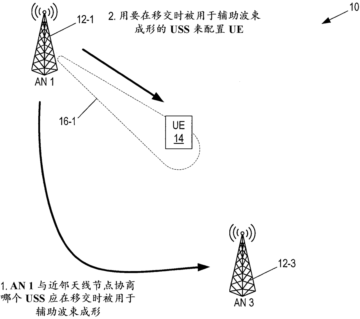
[0052] Antenna Node (AN): As used herein, an "antenna node" or "AN" is a unit capable of generating one or more beams covering a specific area or direction. AN can be a base station or part of a base station.
[0053] User Equipment (UE): As used herein, "UE" is any type of wireless device that has access to a cellular communication network (that is, served by the cellular communication network) by wirelessly transmitting and/or receiving signals to AN . Some examples of UEs include, but are not limited to, mobile phones, tablet computers, and machine type communication (MTC) devices.
[0054] Note that the description given herein focuses on the 3rd Generation Partnership Project (3GPP) cellular communication system, and so often uses 3GPP terminology or terminology similar to 3GPP terminology. However, the concepts disclosed herein are not limited to 3GPP systems.
[0055] UE-specific source beam or source beam: As used herein, "UE-specific source beam" or "source beam" is a beamformed beam that maximizes the energy radiated toward the UE and is currently sending/receiving to/from the UE Used when data.
[0056] UE-specific candidate beam or target beam or neighboring beam: As used herein, "dedicated candidate beam" or "target beam" or "neighbor beam" is a beam-formed antenna that has not been used to send/receive data to/from UE Antenna radiation pattern. Until the UE is actually there and the beamforming mechanism has shaped the beam to match the UE location, this beam usually does not exist, and the UE location may be a geographic location and/or a radio location.
[0057] Broadcast source beam: As used herein, a "broadcast source beam" is a beam used by the source AN to communicate with any or all UEs located in the corresponding area.
[0058] Broadcast candidate beam: As used herein, a "broadcast candidate beam" is a beam used by a candidate AN to communicate with any or all UEs located in the corresponding area.
[0059] Mobility Reference Signal (MRS): As used herein, "MRS" is any signal used for mobility measurement. Therefore, although the term “MRS” is used herein to refer to the signal used in the embodiments of the present disclosure, the term “MRS” should be broadly literally translated to mean any signal, regardless of the name of the signal (for example, in Mobility is measured and specifically according to any specific standards used in the embodiments described herein). In some embodiments, MRS is a mobility specific signal used for handover/beam switching purposes. This signal can be periodic or aperiodic. It can be configured to be UE-specific or can be used in common for more than one UE. The MRS is encoded to allow the UE to distinguish one MRS from another MRS, where indexing is one such way of encoding the MRS. For example, MRS can be unique to a certain index. In some specific embodiments, the MRS design (potentially and functionally) is similar to the primary synchronization signal (PSS)/secondary synchronization signal (SSS) design (potentially and functionally) in 3GPP Long Term Evolution (LTE). Note that the terms "mobility reference signal" and "measurement reference signal" are used interchangeably herein.
[0060] Uplink synchronization signal (USS): As used herein, "USS" is any uplink synchronization signal used to provide channel quality estimation and/or synchronization, for example, in the uplink. It is worth noting that although the term "USS" is used in this article to refer to this type of synchronization signal, the term "USS" should be literally translated in a broad sense to mean any signal, regardless of the name of the signal (for example, when used for mobility measurement) And specifically in accordance with any specific standards used in the embodiments described herein). In some embodiments, USS is used for uplink timing advance calculation, uplink frequency offset estimation, and/or uplink beam identification. In some embodiments, the USS is a random access preamble (eg, the same as or similar to the physical random access channel (PRACH) preamble in LTE). In some embodiments, USS is mapped to a specific MRS. For example, USS timing may be mapped to MRS timing and/or USS sequence may be mapped to MRS sequence.
[0061] The present disclosure relates to cellular networks, for example, fifth-generation (5G) cellular networks, and specifically relates to how to efficiently handle beam switching mobility in poor coverage. It should be noted that although the term "beam switching" is sometimes used herein, beam switching may be interchangeably referred to as handover, node switching, access point switching, or the like.
[0062] Beamforming introduces the possibility of enhancing the signal towards a specific location. This enables better signal-to-noise ratio towards a specific UE and better interference isolation towards UEs served by another beam.
[0063] Some services are not UE-specific, that is, they need to serve multiple UEs that are not located in exactly the same location. These services will use beams that are less focused towards a specific UE but instead cover a wider area.
[0064] The above scenario creates a difference in how the UE perceives the broadcasted service compared to the service dedicated to a single UE. By using less efficient but more robust modulation for the broadcast service, some differences can be reduced. Broadcast services are widely used in today's mobile radio networks to determine when and towards which mobility actions should be performed. An example is cell measurement in LTE. In systems like 5G, where beamforming will be heavily used, the difference between broadcast and dedicated services will make it more difficult to compare and determine when and towards what mobility actions should be performed.
[0065] In this solution, the radio system can recognize and prevent the difference in signal strength from UE-specific signaling and signaling for broadcast services (such as signaling for mobility measurement) in terms of signal strength. Potential radio link failure to switch mobility. Specifically, the radio system can compensate for differences in signal strength from beamformed UE-specific reference signals used for, for example, demodulation reference signals (DMRS), resulting in an improved amount of energy radiated toward the UE (unrelated to usage Compared with the amount of energy radiated toward the UE of the beamforming MRS at a specific UE location). In other words, MRS is a broadcast beam.
[0066] When beam switching is desired for a specific UE currently served by a source beam, multiple candidate beams must be measured by the UE before beam switching to ensure that the target beam selected for beam switching is not worse than the source beam. However, due to the difference between the dedicated beam to this UE and the beam used to indicate the broadcast for the mobility area of ​​the candidate beam, and since the UE may not even be able to hear the broadcast candidate beam, it is difficult for the UE to decide whether to perform the beam Handover, because it is difficult for the UE to determine the relationship between the broadcast candidate beam and the fully beamforming dedicated candidate beam in the same antenna node.
[0067] In some embodiments, the solution is to provide the UE with a configuration of the USS that can be sent, which will then initiate another MRS transmission, which will beamform as much as possible based on the received USS signal. In some embodiments, USS is similar to sounding reference signal (SRS) and/or PRACH preamble in LTE. The beamformed MRS can then be compared with the beamformed dedicated source beam. The UE configuration or activation will be applied before the beam switching attempt, which contains details about the USS to be used and how long to wait before initiating transmission of the USS. Note that USS should generally be avoided because it will contaminate radio conditions. This can also be combined by informing the candidate beam about this UE and which USS the UE will use if the timer expires (based on the threshold configured by the source beam). The candidate beam can use the received USS to beamform a specific MRS (or use the same MRS as previously used in wide beam broadcasting).
[0068] Using the embodiments of the present disclosure provides the following non-limiting advantages:
[0069] • Improve the success rate of beam switching mobility at least in some cases
[0070] • Improved the selection of the best candidate beam for beam switching mobility
[0071] • Ability to deal with differences in coverage between source and target beams caused by unfair beamforming comparisons
[0072] • Reduce the drop risk and associated increased signaling in the radio access network (RAN)
[0073] • Reduce the need to use persistent high output power for broadcast services such as MRS.
[0074] figure 1 An example of a wireless system 10 (which may also be referred to as a radio system 10 herein) is shown, in which an embodiment of the present disclosure may be implemented. As shown, the wireless system 10 includes a plurality of ANs 12-1 to 12-3 that operate to provide wireless access to UEs such as UE 14. In this specific example, the UE 14 transmits and/or receives signals, such as data signals and/or control signals, to AN 12-1 via the UE-specific source beam 16-1. The UE-specific source beam 16-1 is also referred to herein as the source beam 16-1 of the UE 14. The MRS is transmitted to the UE 14 on the source beam 16-1. As such, this MRS is referred to herein as a beamformed MRS, that is, an MRS transmitted on the UE-dedicated source beam 16-1. This MRS is in figure 1 Known as MRS E.
[0075] The embodiments of the present disclosure involve beam switching, that is, the handover of the UE 14 from the source beam 16-1 to the target beam. In this regard, AN 16-2 and 16-3 transmit corresponding MRSs (which are called MRS A and MRSC) on broadcast candidate beams 16-2 and 16-3, respectively. However, the problem is caused by the fact that MRS A and C are transmitted on the broadcast candidate beams 16-2 and 16-3, and the source beam 16-1 is a beam-formed UE-specific beam. Specifically, in some situations, the UE 14 may not be able to detect the MRS transmitted on the broadcast candidate beams 16-2 and 16-3. In other situations, even if the UE 14 can detect the MRS transmitted on the broadcast candidate beams 16-2 and 16-3, the received power of the MRS may be too low to trigger beam switching. The embodiments of the present disclosure solve this problem.
[0076] In an embodiment of the present disclosure, a radio system such as the wireless system 10 can recognize and prevent radio link failure and failed handover by compensating for differences in: (a) signal strength from UE-specific beam signaling, that is, Beamformed UE-specific reference signals such as DMRS; and (b) signal strength from signaling used for broadcast services, such as those used for mobility measurement (ie MRS). In other words, the wireless system 10 compensates for differences in: (a) the signal strength of the source beam 16-1 at the UE 14, that is, the beamformed UE-specific reference received by the UE 14 on the source beam 16-1 The signal strength of the signal (eg, DMRS) at the UE 14; and (b) the signal strength of the MRS received by the UE 14 on the broadcast candidate beams 16-2 and 16-3 (if any) at the UE 14. Since dedicated signaling strives to maximize the amount of energy radiated towards UE 14 (whereas broadcast signals generally use beamforming that is not specific to the location of a particular UE but covers a larger area serving many UEs), discrepancies may occur.
[0077] Moreover, when beam switching is about to occur, the dedicated signaling in the source beam has a much better link than candidate beams 16-2 and 16-3 that have not yet performed link adaptation (ie, beamforming) towards the UE 14. Road adaptation (implemented using beamforming). The broadcast candidate beams 16-2 and 16-3 are identified by sending the MRS, and the UE 14 reports back the best candidate or reply to match the USS of the selected MRS, which can also allow beam switching to occur. The latter case considers the situation in which each MRS is mapped toward a specific USS, thereby allowing the system to use the USS as a trigger to perform beam switching, that is, when an AN that sends a broadcast candidate beam of a certain MRS hears a certain USS, it This will be used as a handover trigger.
[0078] However, there are some situations where the MRS transmitted on the broadcast candidate beams 16-2 and/or 16-3 is too low or not detected by the UE 14 at all, which prevents any beam switching, and in the worst case This results in a radio link failure of the UE 14, which will cause an unwanted interruption in data transfer, and also increase resource allocation and signal load on the RAN when the UE 14 attempts to reconnect.
[0079] One scenario is that the UE 14 will leave the coverage of one AN, as reported by measurement or detected by the UE-specific source beam 16-1 using reciprocity. More specifically, UE 14 will leave the coverage of AN 12-1 (referred to herein as source AN 12-1) corresponding to source beam 16-1. The UE 14 is then configured to use MRS search to search for new candidate beams. Alternatively, the UE 14 may already use the threshold to configure when to start the candidate measurement.
[0080] If the UE 14 detects only a too low MRS or does not detect the broadcast candidate beam 16-2 or 16-3 (ie, MRS) at all (not including the AN 12-1 that is the same as the dedicated source beam 16-1) MRS), the problem occurs. A "too low MRS" is an MRS that has a received signal strength or quality less than a predefined or pre-configured threshold at the UE 14. E.g, figure 2 It shows a situation where the UE 14 is getting worse coverage than the threshold of the UE-dedicated source beam 16-1, but the broadcast candidate beam (MRS C in this example) cannot be detected. This disclosure describes two options for solving this problem. Various embodiments of these two options are described below. Note that the dotted lines around the dedicated source beam 16-1 show the coverage and beamforming of the dedicated source beam 16-1.
[0081] Option 1
[0082] Option 1 in image 3 Is shown in. After, for example, the time period that can be configured in the UE 14 has expired since the start of the MRS search, the UE 14 reports zero results through the UE-dedicated source beam 16-1 or reports back as another option any MRS heard. Too low signal. In other words, UE 14 reports that it has not detected any MRS or any detected MRS is too weak. If, for example, the signal-to-interference and noise ratio (SINR) or the received signal strength/quality value of the detected MRS is lower than a predefined or pre-configured threshold, the detected MRS is considered too weak. The AN 12-1 serving the UE-specific source beam 16-1 (referred to herein as the source beam AN) can then command or instruct one or more other ANs (such as, for example, one or more neighbor ANs, such as in the illustrated example AN 12-3) Increase the output power on MRS transmission, or in other words, increase the MRS transmission power on the broadcast candidate beam 16-3. At least in some embodiments, the instruction for increasing the MRS transmission power is an instruction for temporarily increasing the MRS transmission power. The temporary increase in MRS transmission power may be, for example, at least long enough to allow the UE 14 to make new measurements with some margin. As an example, in e.g. New Radio Access Technology (RAT) (NR), a single MRS transmission may be sufficient (this means that the temporary increase in MRS transmission power is a few milliseconds), but if a more robust trigger time is desired, The temporary increase in MRS transmission power can last several hundred milliseconds. Once the temporary increase in MRS transmission power is triggered, the UE 14 will continue the MRS search/measurement (for example, even after delivering a failure report that triggers an instruction to increase the MRS transmission power), or the source AN 12-1 can order the UE 14 Perform a new MRS search/measure (when instructing candidate AN(s) (for example, AN 12-2 and/or 12-3) to increase MRS transmission power).
[0083] In an alternative embodiment, if the source AN 12-1 orders a measurement, the lack of a response from the UE 14 may trigger the transfer from the source AN 12-1 to the candidate AN 12-2 and/or 12-3. Command to increase MRS transmission power. Source AN 12-1 corresponds to image 3 AN 1 in the example, and candidate AN 12-2 and/or 12-3 corresponding to image 3 AN 3 in the example.
[0084] Figure 4 The operation of the UE 14, the source AN 12-1, and one or more candidate AN 16-2, 16-3 for Option 1 according to some embodiments of the present disclosure is shown. Optional steps are indicated by dashed lines. Note that, as used herein, "source AN" is the AN associated with the source beam, and "candidate AN" is the AN associated with the candidate beam. As shown, the source AN 12-1 optionally configures the UE 14 to perform MRS search (step 100). This configuration may include, for example, a timer value to be used by the UE 14 to determine when to trigger the report in step 106 below. This configuration may also include, for example, matching USS information for the MRS of the candidate beam.
[0085] At a certain point in time, the UE 14 performs an MRS search to, for example, determine whether there are any suitable candidate beams for beam switching (step 102). For example, the UE 14 searches for an MRS with a received signal strength greater than a predefined or pre-configured threshold. For example, this threshold can be configured in step 100. Optionally, the UE 14 determines that one or more conditions for initiating an event to increase the MRS transmission power of the candidate AN(s) 16-2, 16-3 are satisfied (step 104). These conditions may include, for example, the expiration of a timer, which may be configured with a timer value before detecting an MRS or before detecting an MRS with an SINR greater than a predefined or preconfigured threshold (for example, in step 100). Note that SINR is just an example. Any other signal strength or signal quality value can be used. If the condition(s) is met, the UE 14 sends a report to the source AN 12-1 indicating that the UE 14 did not detect the MRS or any MRS(s) detected by the UE 14 is too low/ Weak, for example, having an SINR value less than a predefined or pre-configured value (step 106). Upon receiving the report, the source AN 12-1 instructs one or more candidate AN 12-2, 12-3 to increase its MRS transmission power (step 108). The one or more candidate AN 12-2, 12-3 may be, for example, one or more neighbor AN. At least in some embodiments, this instruction is an instruction for temporarily increasing the MRS transmission power of one or more candidate AN 12-2, 12-3. In response, the candidate AN(s) 12-2, 12-3 temporarily increases the MRS transmission power (step 110).
[0086] As will be appreciated by those of ordinary skill in the art, when the increased transmission power is used to transmit the MRS of one or more candidate AN 12-2, 12-3 on the broadcast candidate beam 16-2, 16-3, the UE 14 At least one of the MRSs having received power greater than a predefined or pre-configured threshold is detected. The UE 14 reports the detected MRS(s) and, in some embodiments, reports to the source AN 12-1 an indication of the received power or quality of the detected MRS(s). Then, the source AN 12-1 initiates beam switching for the selected or best MRS among the MRS(s) reported by the UE 14 from the source beam 16-1 to the UE 14 from the source beam 16-1.
[0087] Option 2
[0088] in Figure 5 , 6 The aspect of option 2 is shown in and 7. Figure 5 The negotiation process between ANs is shown, which is used to determine the USS to be used by the UE 14 to trigger the auxiliary beamforming of the MRS. In the example shown, the negotiation process is between AN 12-1 and 12-3. As shown, in this example, the source AN 12-1 and the neighbor AN 16-3 negotiate the USS to be used by the UE 14 to trigger the auxiliary beamforming of the MRS. Then, the source AN 12-1 configures the UE 14 through the USS to be used by the UE 14 to trigger the auxiliary beamforming of the MRS.
[0089] Image 6 Shows the transmission of the configured USS through the UE 14, which is used to trigger the transmission of the assisted beamformed MRS(s) through the candidate AN(s), the (one or more) The candidate AN in this example is or includes AN 12-3. As shown, upon determining that it is to trigger the transmission of the assisted beamformed MRS through the candidate AN(s), the UE 14 transmits the configured USS. In this example, in a case where the UE 14 does not detect any MRS or in a case where the UE 14 does not detect any MRS with a received power or quality (for example, received SINR) greater than a predefined or pre-configured threshold, the UE 14 Determine that it wants to trigger the transmission of the assisted beamformed MRS through the candidate AN(s) when the timer expires after the MRS search starts.
[0090] Figure 7 The transmission of the beamformed MRS through the candidate AN 12-3 when the USS is received from the UE 14 is shown. As shown, upon receiving the USS from the UE 14, the candidate AN 12-3 transmits MRS (MRS C) through beamforming in the direction in which the USS is received from the UE 14. In other words, the candidate AN 12-3 transmits the MRS (MRS C) on the UE-specific candidate beam 16-3' (in the direction in which the USS is received from the UE 14).
[0091] In operation, after a period of time since the start of the MRS search, the UE 14 sends a USS configured for the UE 14 and not associated with any MRS to trigger the passage of the candidate AN(s) (such as AN 12-2 and/ Or AN 12-3) the transmission of beamformed MRS. The beamformed MRS transmitted by the candidate AN is also referred to herein as the MRS transmitted on the UE-specific candidate beam. Each AN except for the source AN 12-1 that received the USS from the UE 14 transmits the beam-formed MRS in the same direction as the receiving USS using a beam more accurate than that used for normal MRS transmission. The direction of receiving the USS may be determined based on the channel estimation using the received USS. When the MRS transmission is received at the UE 14, the UE 14 can: (a) report the detected (eg best) MRS back to the source AN 12-1, where the source AN 12-1 can then try to resolve which candidate AN Or which neighbor AN transmits the MRS and initiates beam switching to the candidate AN; or (b) transmits the USS that matches the detected (for example, the best) MRS to the candidate AN, and performs beam switching from there. Note that (a) is referred to as "option 2a" herein, and (b) is referred to as "option 2b" herein.
[0092] The UE beam search can be configured or activated. The UE beam search is also referred to herein as MRS search. As part of the configuration or activation, if the MRS is not heard, the specific USS to be used can be assigned to the UE 14. The source AN 12-1 can inform the candidate AN 12-2 and 12-3 about which USS will be used by the UE 14 to trigger the auxiliary beamforming of the MRS (if not enough MRS is heard); and optionally which MRS should be used as the pair This particular USS reply is sent. Again, in some examples, candidate AN 12-2 and 12-3 are neighbor ANs that provide candidate (eg, neighbor) beams.
[0093] In option 2, as for example Figure 5 And as described below Figure 8 with 9 The configuration steps shown in can be used for the configuration of the USS (for example, in the case of Active Mode Mobility (AMM) when the UE 14 is in RRC_CONNECTED mode), which is used to trigger the auxiliary beamforming of the MRS. This is because the USS resource used for this process must be unique or orthogonal to the USS resource reserved by the neighboring node based on its MRS-to-USS mapping (which is used for example for conventional beam switching) to avoid the detected USS May misinterpret. The USS used for the purpose of this disclosure need not be unique among all UEs, because the purpose is only to notify the node that hears the USS to temporarily beamform its MRS in this direction, but if required by a certain situation, It can be unique.
[0094] Note that in some AMM schemes, a certain USS is mapped to a certain MRS, and the UE 14 can use the USS corresponding to its MRS to perform access to the new node. Therefore, if the USS is mapped towards a certain MRS, the AN will know to which MRS the UE 14 is responding. For example, if USS 1 to 3 are mapped to MRS 1 to 3 and if UE 14 hears MRS 1 to 3 but MRS 2 is the best, UE 14 will reply with USS 2. Then, the AN sending MRS 2 knows that this USS is intended for it. Moreover, the AN sending MRS 1 and 3 knows that this USS is not intended for them.
[0095] Figure 8 The operation of the UE 14, the source AN 12-1, and one or more candidate AN 12-2, 12-3 for option 2a according to some embodiments of the present disclosure is shown. Optional steps are indicated by dashed lines. As shown, optionally, the source AN 12-1 and one or more candidate AN 12-2 and/or 12-3 negotiate a USS for the UE 14 (step 200). This USS is a USS or USS resource to be used by the UE 14 to trigger auxiliary beamforming through the MRS of candidate AN 12-2 and/or 12-3. Moreover, the source AN 12-1 optionally configures the UE 14 (step 202). This configuration may include, for example, a USS to be used by the UE 14 to trigger auxiliary beamforming of MRS. Additionally or alternatively, this configuration may also include, for example, matching of the USS information to the MRS of the candidate beam. The configuration may also include a timer value to be used by the UE 14 to determine when to trigger the transmission of the USS in step 208.
[0096] At a certain point in time, the UE 14 performs an MRS search to, for example, determine whether there are any suitable candidate beams for beam switching (step 204). Optionally, the UE 14 determines that one or more conditions for initiating assisted MRS beamforming are satisfied (step 206). This condition(s) may include, for example, the expiration of a timer configured with a timer value (for example, before detecting MRS in step 202 or after detecting an SINR greater than a pre-defined or pre-configured threshold Or other signal strength or signal quality values ​​before MRS). If the condition(s) are met, the UE 14 transmits a USS to trigger auxiliary MRS beamforming (step 208).
[0097] The candidate AN 12-2 and/or 12-3 detects the USS transmitted by the UE 14 (step 210). When the USS transmitted by the UE 14 is detected, the candidate AN 12-2 and/or 12-3 transmits the MRS through beamforming in the direction of receiving the USS from the UE 14 (step 212). In other words, the candidate AN(s) 12-2 and/or 12-3 transmits the beamformed MRS towards the UE 14, where the beamforming is based on the channel implemented with the help of the USS transmitted by the UE 14. estimate. In this context, MRS is said to be transmitted on the UE-specific candidate beam.
[0098] UE 14 optionally detects one or more beamformed MRS (step 214). In this embodiment, the UE 14 reports the detected MRS to the source AN 12-1 (step 216). The detected MRS reported by the UE 14 is, for example, the best MRS detected by the UE 14, which may be a beamformed MRS. In some embodiments, UE 14 reports that a USS triggered process has occurred. This information can be used by the source AN 12-1 for statistics, but can also be used to evaluate the results with knowledge that the MRS heard by the UE 14 may have been beamformed. If the UE 14 does not report this, it can still use the information exchange with the candidate AN 12-2, 12-3 to be determined by the RAN. Then, the source AN 12-1 may try to resolve which candidate AN 12-2 or 12-3 transmitted the reported/best MRS and initiate beam switching to that candidate AN 12-2, 12-3 (step 218).
[0099] Picture 9 The operation of the UE 14, the source AN 12-1, and one or more candidate AN12-2 and/or 12-3 for option 2b according to some embodiments of the present disclosure is shown. Optional steps are indicated by dashed lines. Steps 300 until 314 are with Figure 8 The steps 200 to 214 are the same, and therefore the details of those steps are not repeated.
[0100] In this embodiment, upon detecting one or more beamformed MRS, the UE 14 transmits a USS that matches the detected (eg, best) beamformed MRS (step 316). In this way, the UE 14 replies to the corresponding candidate AN 12-2 or 12-3. From there, the UE 14, the source AN 12-1 and the candidate AN 12-2 or 12-3 perform beam switching (step 318). For example, UE 14 may be configured with candidate AN parameters (eg, similar to what was done for handover in LTE), or may allow candidate beams to "borrow" parameters from the source beam and continue as it is. In the latter case, UE 14 may not even pay attention to beam switching. However, these are just examples. Any suitable technique or methodology can be used to perform beam switching.
[0101] Notable aspects of embodiments of the present disclosure
[0102] Some notable aspects of this disclosure are as follows:
[0103] • Configure the UE 14 conditions and timers when to use USS to be able to beamforming candidate MRS transmissions.
[0104] • Configure the UE 14 with the USS to be used for beamforming to initiate MRS transmission at the candidate node.
[0105] · Notify the neighbor node which USS will be used by a specific UE 14 to allow the target node to beamforming and send the MRS intended for this UE 14 to continue the beam switching mobility process.
[0106] • Use conditions and timers to trigger events that increase the output power of the MRS for candidate beams.
[0107] AN and UE block diagram
[0108] Picture 10 It is a schematic block diagram of AN 12 according to some embodiments of the present disclosure. AN 12 may be the source AN 12-1 or one of the candidate AN 12-2 and 12-3. As shown, the AN 12 includes a control system 18 that includes one or more processors 20, a memory 22, and a network interface 24. The one or more processors 20 are, for example, a central processing unit (CPU), an application specific integrated circuit (ASIC), a field programmable gate array (FPGA), and/or the like. In addition, the AN 12 includes one or more radio units 26, each of the one or more radio units 26 including one or more receivers 30 and one or more transmitters 28 coupled to one or more antennas 32. In some embodiments, the radio unit(s) 26 is external to the control system 18 and is connected to the control system 18 via, for example, a wired connection, such as, for example, a fiber optic cable. However, in some other embodiments, the radio unit(s) 26 and potential antenna(s) 32 are integrated with the control system 18. One or more processors 20 operate to provide one or more functions of AN 12 as described herein. In some embodiments, the function(s) is implemented by software, and the software is stored in the memory 22 and executed by one or more processors 20, for example.
[0109] Picture 11 It is a schematic block diagram showing a virtualization embodiment of AN 12 according to some embodiments of the present disclosure. This discussion can also be applied to other types of network nodes. In addition, other types of network nodes can have similar virtualized architectures.
[0110] As used herein, a "virtualized" AN is an implementation of AN 12, where at least part of the functionality of AN 12 is executed, for example, via physical processing node(s) in the network(s) ( One or more virtual machines are implemented as virtual component(s). As shown, in this example, the AN 12 includes a control system 18, which includes one or more processors 20 (such as, for example, a CPU, ASIC, FPGA, and/or the like), a memory 22 and a network interface 24, and a One or more radio units 26, one or more radio units 26 each including one or more receivers 30 and one or more transmitters 28 coupled to one or more antennas 32, as described above. The control system 18 is connected to the radio unit(s) 26 via, for example, an optical cable or the like. The control system 18 is connected to one or more processing nodes 34, and the one or more processing nodes 34 are coupled to the network(s) 36 or included as the network(s) 36 via the network interface 24 Part. Each processing node 34 includes one or more processors 38 (such as, for example, a CPU, ASIC, FPGA, and/or the like), a memory 40, and a network interface 42.
[0111] In this example, the functionality 44 of the AN 12 described herein is implemented at one or more processing nodes 34 or distributed across the control system 18 and one or more processing nodes 34 in any desired manner. In some specific embodiments, some or all of the functions 44 of the AN 12 described herein are implemented as one or more virtual machines (in the virtual environment(s) hosted by the processing node(s) 34) In) the virtual component that is executed. As will be appreciated by those of ordinary skill in the art, additional signaling or communication between the processing node(s) 34 and the control system 18 is used in order to perform at least some of the desired functions 44. It is worth noting that in some embodiments, the control system 18 may not be included. In this case, the radio unit(s) 26 directly communicates with (one or more) via the appropriate network interface(s). A) processing node 34 for communication.
[0112] In some embodiments, there is provided a computer program including instructions that, when executed by at least one processor, cause the at least one processor to execute the AN 12 or a node according to any of the embodiments described herein (such as, for example, , Realize the functionality of the processing node 34) of one or more functions of AN 12 in the virtual environment. In some embodiments, a carrier including the aforementioned computer program product is provided. The carrier is one of an electronic signal, an optical signal, a radio signal, or a computer-readable storage medium (for example, a non-transitory computer-readable medium such as a memory).
[0113] Picture 12 It is a schematic block diagram of AN 12 according to some other embodiments of the present disclosure. AN 12 includes one or more modules 46, each of which is implemented in software. The module(s) 46 provides the functionality of AN 12 described herein. For example, in some embodiments where AN 12 is the source AN 12-1, module(s) 46 includes a configuration module 46-1 that is operable to configure UE 14 with a USS as described herein. Furthermore, in some embodiments where AN 12 is the source AN 12-1, the module(s) 46 may also include an instruction receiving module 46-2, which is operable to receive from the UE 14 performed by the UE 14 in an attempt to detect An indication (such as, for example, an MRS report) that the MRS search of the MRS transmitted by the candidate AN 12-2 and/or 12-3 is unsuccessful, as described above, and the instruction module 46-3, which can Operate to instruct at least one candidate AN 12-2 or 12-3 to temporarily increase the MRS transmission power when the instruction is received through the instruction receiving module 46-2. In other embodiments where AN 12 is a candidate AN 12-2 or 12-3, the module(s) 46 may include a detection module 46-4 and a transmission module 46-5, and the detection module 46-4 is operable to detect For the USS transmitted by the UE 14, the transmission module 46-5 is operable to transmit the MRS through beamforming in the direction in which the USS is received from the UE 14 when the USS is detected by the detection module 46-4. In other embodiments where AN 12 is a candidate AN 12-2 or 12-3, the module(s) 46 may include an instruction receiving module 46-6 which is operable to serve the source beam 16-1 of the UE 14. The source AN 12-1 receives the instruction to temporarily increase the MRS transmission power; and the MRS transmission power increase module 46-7, which is operable to temporarily increase the MRS transmission at the candidate AN 12-2, 12-3 when the request is received power. This discussion is equally applicable to Picture 11 The processing node 34, where the module 46 can be implemented at one of the processing nodes 34 or distributed across multiple processing nodes 34 and/or distributed across the processing node(s) 34 and the control system 18.
[0114] Figure 13 It is a schematic block diagram of UE 14 according to some embodiments of the present disclosure. As shown, the UE 14 includes one or more processors 48 (such as, for example, a CPU, ASIC, FPGA, and/or the like), a memory 50, and one or more transceivers 52, each of the one or more transceivers 52 including One or more receivers 56 and one or more transmitters 54 are coupled to one or more antennas 58. In some embodiments, the functionality of the UE 14 described above may be implemented in whole or in part by software, which is stored in the memory 50 and executed by the processor(s) 48, for example.
[0115] In some embodiments, there is provided a computer program including instructions that, when executed by at least one processor, cause the at least one processor to perform the functionality of the UE 14 according to any of the embodiments described herein. In some embodiments, a carrier including the aforementioned computer program product is provided. The carrier is one of an electronic signal, an optical signal, a radio signal, or a computer-readable storage medium (for example, a non-transitory computer-readable medium such as a memory).
[0116] Figure 14 It is a schematic block diagram of UE 14 according to some other embodiments of the present disclosure. The UE 14 includes one or more modules 60, each of which is implemented in software. The module(s) 60 provides the functionality of the UE 14 described herein. For example, in some embodiments, the module(s) 60 includes an MRS search module 60-1 and a transmission module 60-2. The MRS search module 60-1 is operable to perform an MRS search in an attempt to target one or more candidates. Beam to detect the MRS transmitted by one or more candidate AN 12-2 and/or 12-3, the transmission module 60-2 is operable to transmit an indication that the MRS search is unsuccessful (if one or more of the indications that the MRS search is unsuccessful Conditions are met). The indication is, for example, the MRS report in Option 1 and the USS in Option 2 that is configured for the UE 14 to trigger the transmission of beamformed MRS.
[0117] Example embodiment
[0118] Some example embodiments of the present disclosure are provided below, but are not limited thereto.
[0119] 1. A method of operating a user equipment device UE (14) for transmitting and/or receiving on a source beam to and/or from a source antenna node AN, the method comprising:
[0120] · Perform (204, 304) mobility reference signal MRS search to try to detect the MRS transmitted by one or more candidate ANs for one or more candidate beams; and
[0121] · If one or more conditions indicating that the MRS search is unsuccessful are met, then a transmission (208, 308) is configured for the UE (14) to trigger the beamforming through the one or more candidate ANs MRS transmits the uplink synchronization signal USS.
[0122] 2. The method of embodiment 1, wherein the one or more conditions include expiration of a timer.
[0123] 3. The method of embodiment 1, wherein the one or more conditions include a condition that a timer has expired and no MRS is detected during the MRS search.
[0124] 4. The method of embodiment 1, wherein the one or more conditions include a condition that a timer has expired without detecting an MRS with a received signal-to-interference-to-noise ratio (SINR) higher than a predefined or pre-configured threshold.
[0125] 5. The method according to any one of embodiments 1 to 4, further comprising receiving (202) the configuration of the USS from the source AN of the UE (14).
[0126] 6. The method according to any one of embodiments 1 to 5, further comprising after transmitting (208) the USS:
[0127] · Detect (214) the MRS transmitted by at least one of the candidate ANs; and
[0128] · Report (216) the MRS to the source AN.
[0129] 7. The method according to any one of embodiments 1 to 5, further comprising after transmitting (308) the USS:
[0130] · Detect (314) the MRS transmitted by at least one of the candidate ANs; and
[0131] · Transmit (316) the USS matching the MRS detected by the UE (14).
[0132] 8. A user equipment device UE (14) for transmitting and/or receiving on a source beam to and/or from a source antenna node AN, the UE (14) is adapted to:
[0133] • Perform a mobility reference signal MRS search to try to detect the MRS transmitted by one or more candidate ANs for one or more candidate beams; and
[0134] · If one or more conditions indicating that the MRS search is unsuccessful are met, transmit an uplink configured for the UE (14) to trigger the transmission of the beamformed MRS through the one or more candidate ANs Link synchronization signal USS.
[0135] 9. The UE (14) according to embodiment 8, wherein the UE (14) is further adapted to operate according to the method according to any one of embodiments 2 to 7.
[0136] 10. A user equipment device UE (14) for transmitting and/or receiving on a source beam to and/or from a source antenna node AN, the UE (14) comprising:
[0137] · At least one transmitter (54) and at least one receiver (56);
[0138] · At least one processor (48); and
[0139] A memory (50), the memory (50) stores instructions executable by the at least one processor (48), whereby the UE (14) is operable to:
[0140] -Perform a mobility reference signal MRS search to try to detect the MRS transmitted by one or more candidate ANs for one or more candidate beams; and
[0141] -If one or more conditions indicating that the MRS search is unsuccessful are met, transmit an uplink configured for the UE (14) to trigger the transmission of the beamformed MRS through the one or more candidate ANs Link synchronization signal USS.
[0142] 11. A user equipment device UE (14) for transmitting and/or receiving on a source beam to and/or from a source antenna node AN, the UE (14) comprising:
[0143] Mobility reference signal MRS search module (60-1), the mobility reference signal MRS search module (60-1) is operable to perform MRS search to try to detect one or more candidate beams by one or more candidate beams MRS transmitted by AN; and
[0144] Uplink synchronization signal USS transmission module (60-2), the uplink synchronization signal USS transmission module (60-2) is operable to transmit if one or more conditions indicating that the MRS search is unsuccessful An uplink synchronization signal USS configured for the UE (14) to trigger the transmission of the beamformed MRS through the one or more candidate ANs.
[0145] 12. A method of operating a source antenna node AN for transmitting and/or receiving on a source beam to and/or from a user equipment device UE (14), the method comprising:
[0146] • Configure (202, 302) the UE (202, 302) with an uplink synchronization signal USS to be used by the UE (14) to trigger transmission of the beamformed mobility reference signal MRS through one or more candidate ANs 14).
[0147] 13. The method as described in embodiment 12, further comprising:
[0148] • Negotiating (200) with the one or more candidate ANs to determine the USS to be used by the UE (14) to trigger the transmission of beamformed MRS through the one or more candidate ANs.
[0149] 14. The method as described in embodiments 12 to 13, further comprising:
[0150] Receive (216) a report from the UE (14), the report including an indication of the MSR detected by the UE (14); and
[0151] · Determine (218) the candidate AN of the one or more candidate ANs that transmitted the MSR detected by the UE (14); and
[0152] • Initiate (218) a beam switch from the source beam to the target beam provided by the candidate AN for the UE (14).
[0153] 15. A source antenna node AN for transmitting and/or receiving on a source beam to and/or from a user equipment device UE (14), the source AN being adapted to:
[0154] • Configure the UE (14) with an uplink synchronization signal USS to be used by the UE (14) to trigger the transmission of beamformed MRS through one or more candidate ANs.
[0155] 16. The source AN according to embodiment 15, wherein the source AN is further adapted to operate according to the method according to any one of embodiments 13 to 14.
[0156] 17. A source antenna node AN for transmitting and/or receiving on a source beam to and/or from a user equipment UE (14), the source AN (12-1) comprising:
[0157] · At least one processor (20, 38); and
[0158] A memory (22, 40), the memory (22, 40) stores instructions executable by the at least one processor (20, 38), whereby the source AN (12-1) is operable to:
[0159] -Configure the UE (14) with an uplink synchronization signal USS to be used by the UE (14) to trigger the transmission of the beamformed mobility reference signal MRS through one or more candidate ANs.
[0160] 18. A source antenna node AN for transmitting and/or receiving on a source beam to and/or from a user equipment UE (14), the source AN comprising:
[0161] • A configuration module (46-1), the configuration module (46-1) being operable to use the beamformed mobility reference signal MRS to be used by the UE (14) to trigger through one or more candidate ANs The transmission of the uplink synchronization signal USS to configure the UE (14).
[0162] The following abbreviations are used throughout this disclosure.
[0163] • 3GPP Third Generation Partnership Project
[0164] • 5G fifth generation
[0165] •AMM active mode mobility
[0166] • AN antenna node
[0167] •ASIC Application Specific Integrated Circuit
[0168] •CPU Central Processing Unit
[0169] • DMRS demodulation reference signal
[0170] •FPGA Field Programmable Gate Array
[0171] •GHz gigahertz
[0172] • LTE long-term evolution
[0173] •MRS Mobility Reference Signal
[0174] •MTC machine type communication
[0175] •NG Next Generation
[0176] •NR new radio access technology
[0177] • PRACH physical random access channel
[0178] •PSS master sync signal
[0179] •RAN radio access network
[0180] •RAT radio access technology
[0181] •SINR signal to interference noise ratio
[0182] •SRS sounding reference signal
[0183] •SSS auxiliary synchronization signal
[0184] •TR Technical Report
[0185] • UE User Equipment
[0186] •USS uplink synchronization signal
[0187] Those skilled in the art will recognize improvements and modifications to the embodiments of the present disclosure. All such improvements and modifications are considered to be within the scope of the concepts disclosed herein and the appended claims.

PUM

no PUM

Description & Claims & Application Information

We can also present the details of the Description, Claims and Application information to help users get a comprehensive understanding of the technical details of the patent, such as background art, summary of invention, brief description of drawings, description of embodiments, and other original content. On the other hand, users can also determine the specific scope of protection of the technology through the list of claims; as well as understand the changes in the life cycle of the technology with the presentation of the patent timeline. Login to view more.
Why Eureka
Try Eureka