Supercharge Your Innovation With Domain-Expert AI Agents!

A flap retractable control mechanism for rotating wings

A technology of rotating wings and operating mechanisms, applied in the direction of wing adjustment, wing lift efficiency, aircraft parts, etc., can solve the problems that front and rear symmetrical airfoil flaps cannot be applied, and achieve the effect of reducing flow separation

Active Publication Date: 2022-05-31
NORTHWESTERN POLYTECHNICAL UNIV
View PDF12 Cites 0 Cited by
  • Summary
  • Abstract
  • Description
  • Claims
  • Application Information

AI Technical Summary

Problems solved by technology

After searching, Chinese patents 201720453503.3, 201610843800.9 and 201610818679.4 have announced the design of various wing trailing edge flap control mechanisms, but they are all aimed at conventional flaps and cannot be applied to the front and rear symmetrical airfoil flaps of the above structure.

Method used


Image

  • A flap retractable control mechanism for rotating wings
  • A flap retractable control mechanism for rotating wings
  • A flap retractable control mechanism for rotating wings

Examples


Embodiment Construction

[0026] Embodiments of the present invention are described in detail below, and the embodiments are exemplary and intended to explain the present invention, but should not be construed as limiting the present invention.

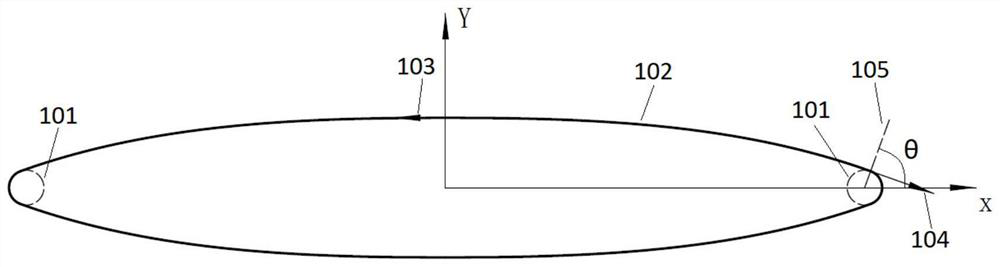
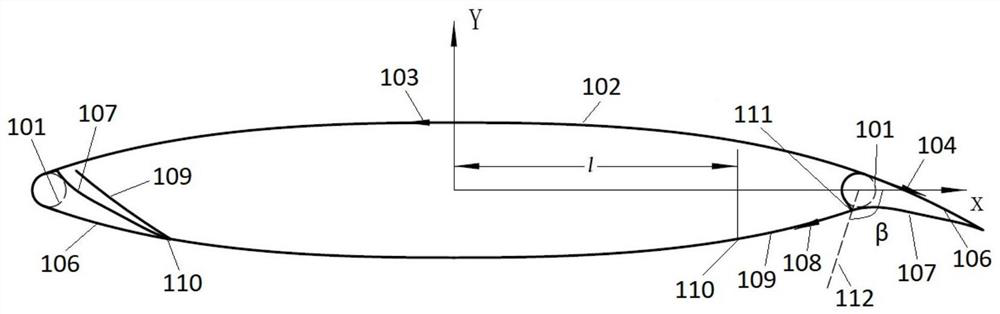
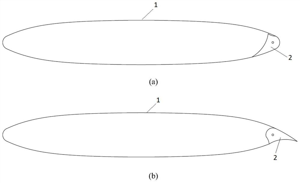
[0027] In this embodiment, flaps are provided at the front and rear ends of the airfoil. In actual use, the flaps on the windward side are folded, and the flaps on the other side are opened. The reason why flaps are set at both ends is that during the rotation, the windward end and the leeward end of the rotating wing on both sides of the rotating shaft are the same, but when the rotating wing stops turning to form a fixed wing, for one side of the rotating shaft When the rotating wing rotates at high speed, the windward end will become the leeward end. At this time, the flap of this end needs to be opened in the fixed-wing flight mode, and the other end changes from the leeward end to the windward side. Flaps retracted. After the flaps are retracted, the sit...


PUM


Abstract

The present invention proposes a flap retractable control mechanism for rotating wings, including flaps, steering steering gear, steering gear connecting rod, flap connecting rod, filling plate connecting rod and filling plate; the steering steering gear is fixed on On the wall panel inside the rotating wing, one end of the connecting rod of the steering gear is fixed on the rotating end of the steering gear, which can be controlled to rotate within the airfoil section of the rotating wing, and the other end of the connecting rod of the steering gear is hinged to one end of the flap connecting rod , the other end of the flap link is hinged to the middle of the inner surface of the flap; the middle of the steering gear link is hinged to one end of the filler plate link, and the other end of the filler plate link is hinged to the inner surface of the filler plate; one end of the filler plate is fixed to the flap opening The rotation axis of the filling plate at the position is matched and can rotate around the rotation axis of the filling plate; the flap is installed on the outer edge of the rotating wing through the rotation axis of the flap. The invention can manipulate the filling plate to cover the concave cavity formed after the flap is opened while controlling the deflection and opening of the flap, so as to prevent the depression from affecting the effect of reducing drag and increasing lift of the flap.

Description

technical field [0001] The invention relates to the technical field of rotary wing design, in particular to a flap retractable control mechanism for a rotary wing. Background technique [0002] The applicant disclosed a rotary wing aircraft with variable flight mode in Chinese patent 201110213680.1. Its biggest feature is that there is a pair of rotary wings in the middle of the fuselage that can rotate at high speed as a rotor and can be locked as a fixed wing. Because it is necessary to take into account the use of both the rotor and the fixed wing, the airfoil of the rotary wing has chosen an elliptical airfoil. [0003] South Korea's Sungyoon Choi and Oh Joon Kwon published "Aerodynamic Characteristics of Elliptic Airfoils at High Reynolds Numbers" in the 45th issue of Jounral of Aircraft, and conducted a numerical calculation study on the aerodynamic characteristics of elliptical airfoils with different relative thicknesses. The results show that because the blunt trail...

Claims


Application Information

Patent Timeline
Patent Type & Authority Patents(China)
IPC IPC(8): B64C9/06B64C3/38
CPCB64C3/38B64C9/06Y02T50/30
Inventor 邓阳平米百刚
Owner NORTHWESTERN POLYTECHNICAL UNIV
Features
  • R&D
  • Intellectual Property
  • Life Sciences
  • Materials
  • Tech Scout
  • Unparalleled Data Quality
  • Higher Quality Content
  • 60% Fewer Hallucinations
Learn More